
Dynamic energy threshold calculation for high impedance fault detection

a high impedance fault and dynamic energy threshold technology, applied in short-circuit testing, emergency protective circuit arrangements, instruments, etc., can solve the problems of downed conductors, public contact with energized lines, and overhead conductors exposed to elements and abnormal conditions,

Active Publication Date: 2006-08-01
ABB (SCHWEIZ) AG
View PDF3 Cites 15 Cited by
  • Summary
  • Abstract
  • Description
  • Claims
  • Application Information

AI Technical Summary

Benefits of technology

This approach enhances HIF detection performance by reducing false detection rates and ensuring reliable identification of faults, providing a robust and adaptive solution for detecting high impedance faults on electrical power lines, thereby improving public safety and minimizing power disruptions.

Problems solved by technology

The overhead conductors are exposed to the elements and to abnormal conditions.
This smaller fault current makes detection of an HIF difficult with conventional protection devices.
The danger with downed conductors is the risk of public contact with the energized lines.
Human contact with downed conductors can result in serious injury or even death.
The problem is further complicated once a downed conductor is detected.
If a relay trips a circuit breaker at a substation, the loss of power to vital public entities, such as hospitals, airports, and traffic signals, can result in life-threatening situations of equal or greater magnitude.
Thus, the problems facing protection engineers are to first detect the type of disturbances and then to react appropriately.
The rate of detection can, therefore, be impaired when the value given to the threshold is fixed since when the steady-state energy level of the phase (load) currents and / or neutral (residual) current for the selected frequency band is high, the false detection rate increases and when it becomes low the false detection rate decreases.
Considering that the steady-state energy level of the input signal depends on the load, it is not practical to set a static threshold that fits all conditions and provides good HIF detection performance.

Method used


Image

  • Dynamic energy threshold calculation for high impedance fault detection
  • Dynamic energy threshold calculation for high impedance fault detection

Examples


Embodiment Construction

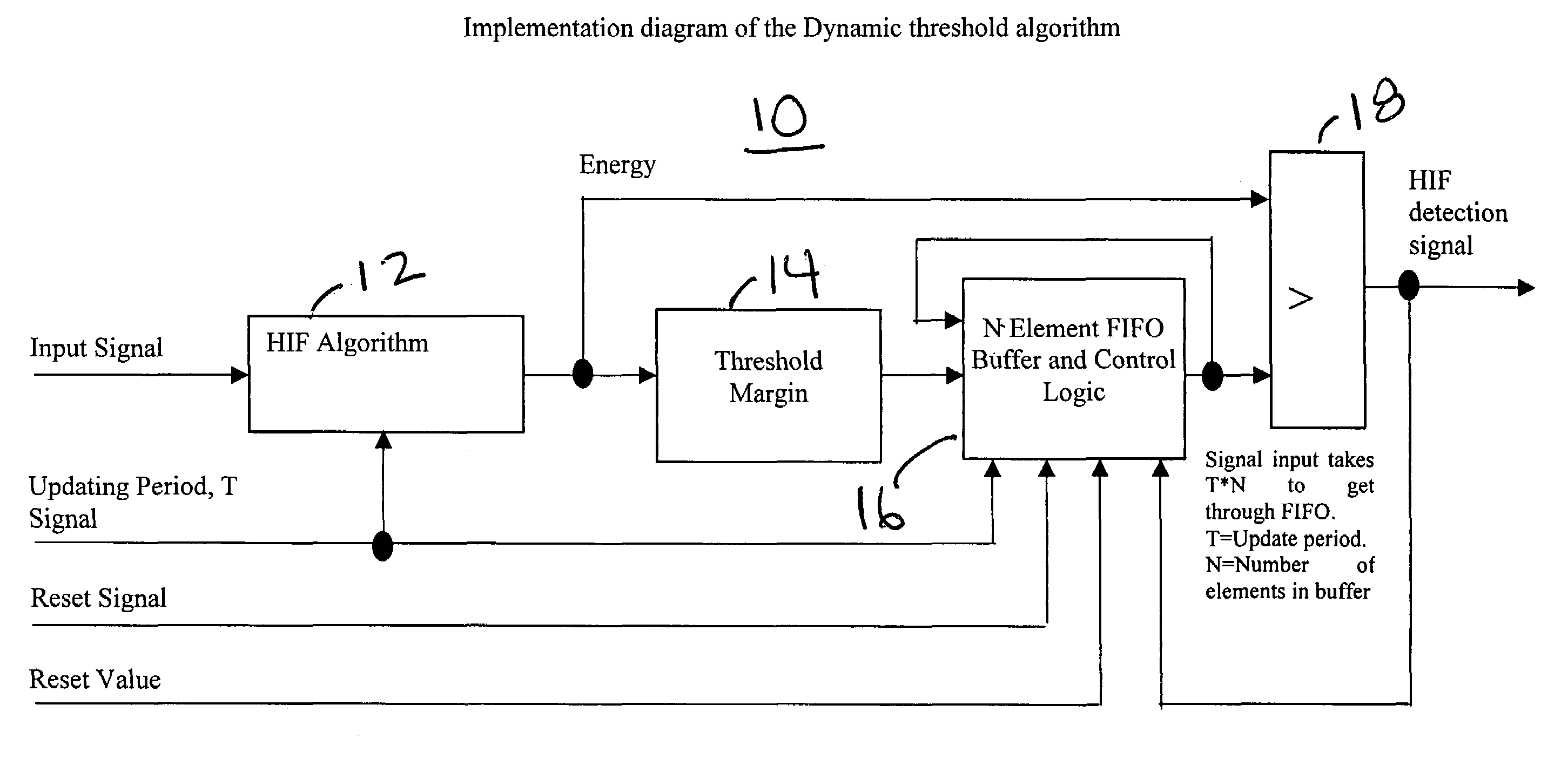
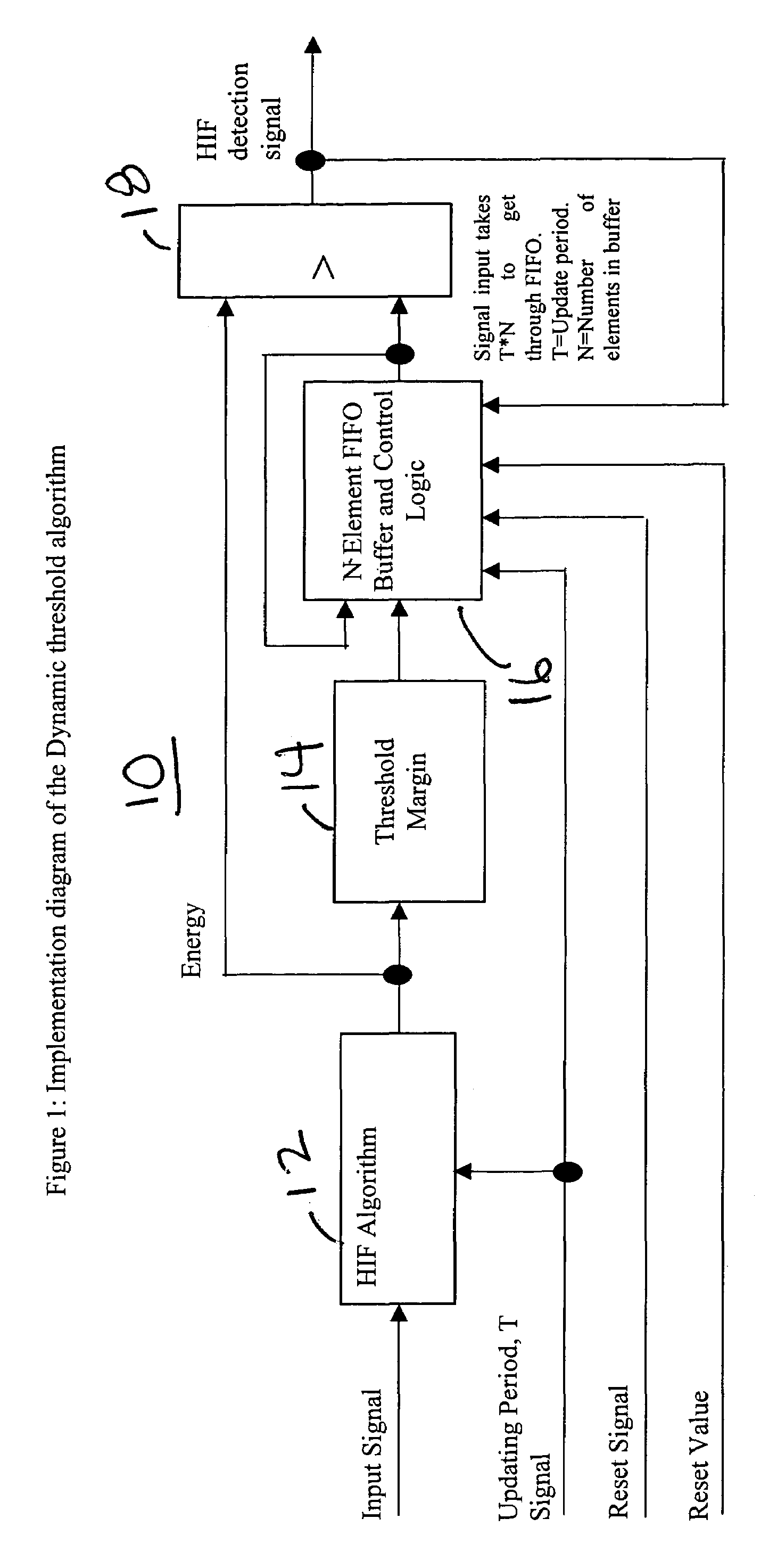
[0026]Referring now to FIG. 1, which is the only drawing figure, there is shown a block diagram for the dynamic energy threshold HIP detection technique 10 of the present invention. The input signal comprising of phase (load) currents and / or neutral (residual) current, is input to the HIF detection algorithm 12 for processing. The HIF detection algorithm 12 may be one of the three algorithms described in the '270 application. The output of the HIF algorithm 12 is the energy of the input signal. This input signal energy is then multiplied by a factor, called Threshold Margin 14, that can be set to a value in the range from about 110% to about 300% depending on the security of detection required. The result of that multiplication, known as Threshold Energy, is stored into a First-In First-Out (FIFO) buffer and control logic 16. Trials with captured field data indicate that there may be an unacceptable number of false detections when using a Threshold Margin lower than 125%. In general...


PUM


Abstract

A technique for dynamically determining the occurrence of a high impedance fault (HIF) independent of load. An HIF algorithm provides the energy value for a given number of samples of the input signal that is phase (load) currents and / or neutral (residual) current. The input signal energy value is multiplied by a factor that ranges from about 110% to about 300% to calculate a threshold energy value and the result of that calculation is stored in a buffer. A HIF detection signal is generated when the energy value determined for samples of the input signal that are the same in number as the given number of samples and taken after the given number of samples is greater than an energy value derived from a predetermined number of the calculated threshold energy values.

Description

BACKGROUND OF THE INVENTION[0001]The present invention is directed toward high impedance fault (HIF) detection and, more particularly, toward a technique to make the detection independent of load.BACKGROUND[0002]Electric utility companies use overhead energized conductors to transport electrical energy to consumers. There are over one million miles of overhead distribution lines in the United States, supplying energy for industrial, commercial, and residential customers. The overhead conductors are exposed to the elements and to abnormal conditions. In some cases, the conductors fall to the ground and, depending on the surface, establish a conducting path. If the surface is grass, soil, or asphalt, a HIF occurs, in which case the fault current is much smaller than that of a typical phase-to-ground fault. This smaller fault current makes detection of an HIF difficult with conventional protection devices.[0003]The danger with downed conductors is the risk of public contact with the en...

Claims


Application Information

Patent Timeline
Patent Type & Authority Patents(United States)
IPC IPC(8): G01R31/00G01R31/50
CPCH02H1/0092H02H1/0015G01R31/025G01R31/1272G01R31/52G01R31/50
Inventor PETERSON, JOHNDAS, RATANHAJ-MAHARSI, MOHAMED Y.
Owner ABB (SCHWEIZ) AG
Learn More