Roller cam assembly

a technology of rolling cams and rolling pins, which is applied in the direction of gearing, gearing elements, hoisting equipment, etc., can solve the problems of not being able to handle any force without inflicting serious deterioration of the cam surface, and severely restricting the capacity of this prior art mechanism to handle torqu

Inactive Publication Date: 2006-08-08
BALLARD RICHARD N
View PDF20 Cites 8 Cited by
  • Summary
  • Abstract
  • Description
  • Claims
  • Application Information

AI Technical Summary

Problems solved by technology

By locating the generating point so far from the surface of the generating pitch circle, the effective component of the forces between the roller and the cam is greatly reduced, thereby severely limiting the capacity of this prior art mechanism to handle torque.
The practical problem with these epicycloidal and cycloidal tooth shapes is that there is one point on the face of each tooth that has a zero-radius of curvature.
And this point will not handle any forces without inflicting serious deterioration of the cam surface.

Method used


Image

  • Roller cam assembly
  • Roller cam assembly
  • Roller cam assembly

Examples


Embodiment Construction

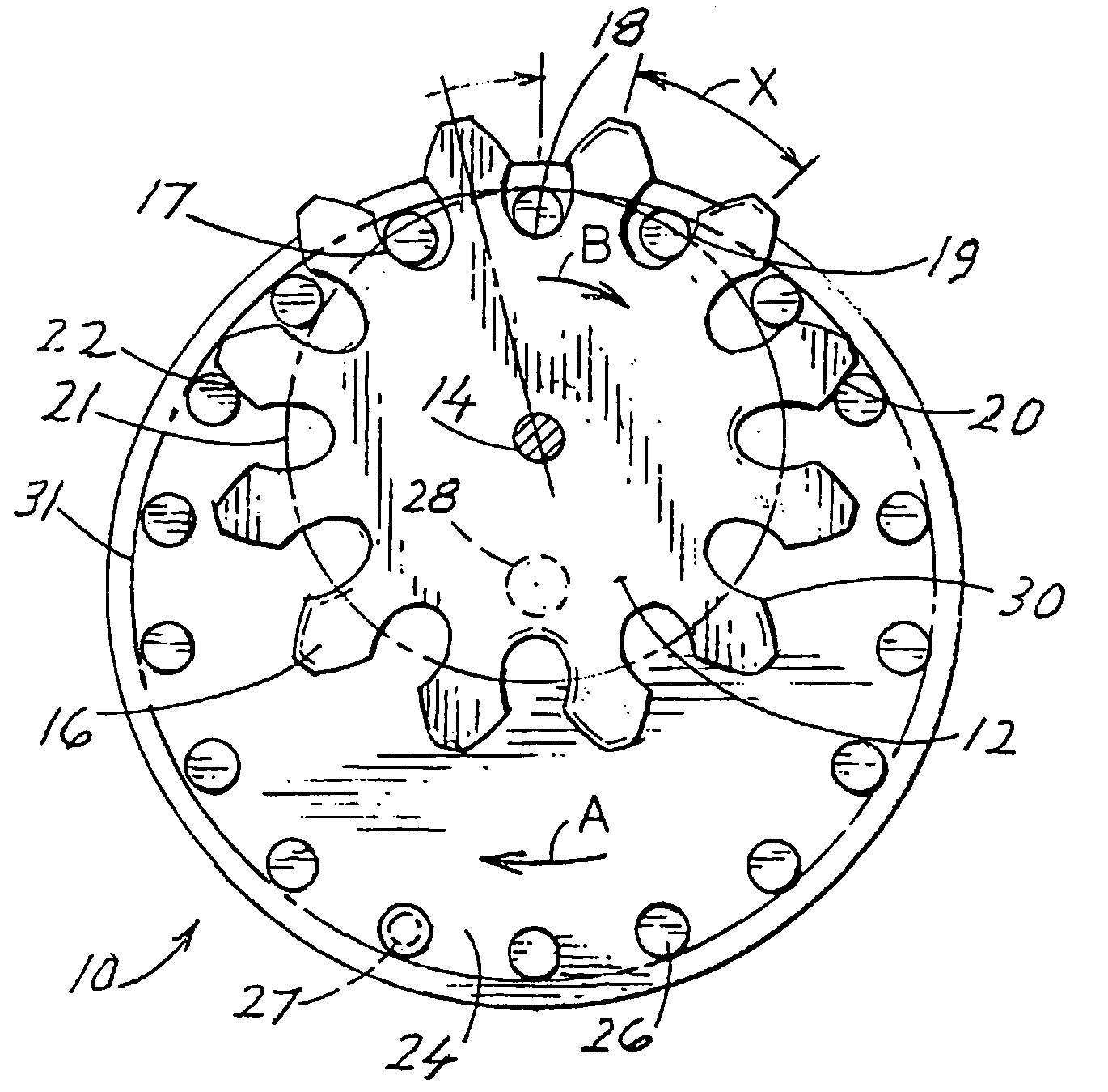
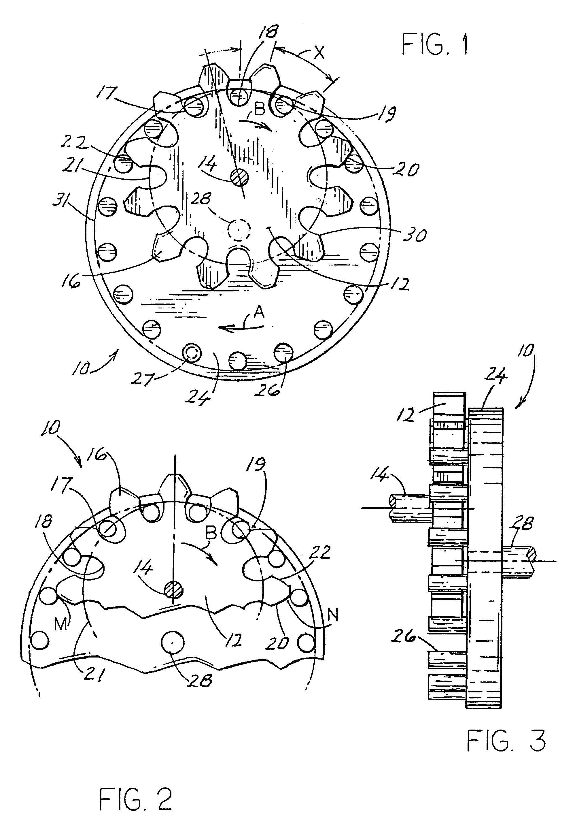
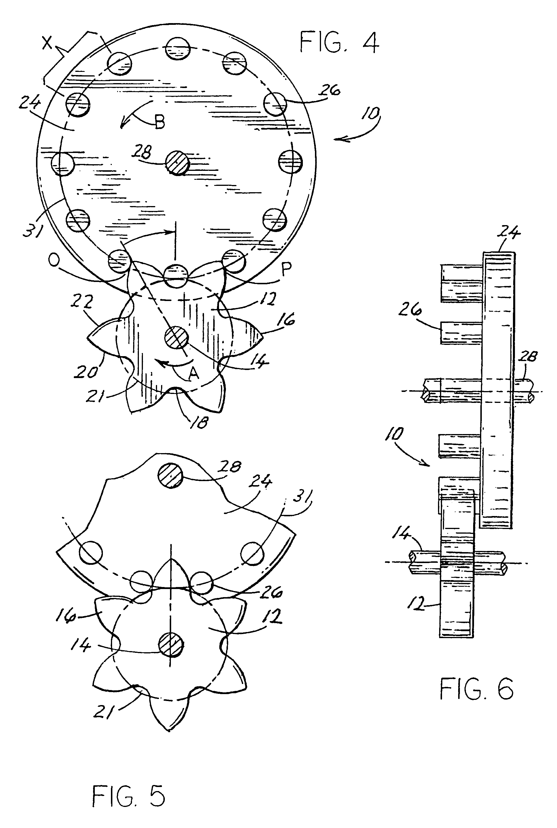
[0032]An understanding of the disclosed roller cam assembly can be best appreciated by referring to the drawing. This disclosure describes four different types of trochoid cam profiles that can interact efficiently with appropriately matched roller ring assemblies. These cam profiles can be described either mathematically or mechanically. This document will do both. The cams can be located internal to the circumference of the roller ring assembly (see FIGS. 1 & 7). Or they can be located externally to the circumference of the roller ring assembly (see FIGS. 4 & 8). Additionally, the cam can also surround the roller ring as in FIGS. 9–12. When the cam is internal or external to the roller ring assembly, but not surrounding the roller ring assembly, it is an epitrochoid cam. In this disclosure, the cams and roller rings move the same as with the gears. The cam shape controls the relative motion between them so as to generate the same output as gears. Herein are described two types of ...


PUM


Abstract

A transmission comprises a pair of drive shafts, one an input shaft and the other an output shaft, wherein one of said shafts is attached to a toothed cam having a trochoidal profile and the other drive shaft is attached to a roller ring having a plurality of cylindrical roller shafts aligned to mesh with said toothed cam and thereby permitting the transfer of torque from one shaft to the other.

Description

[0001]This application is a continuation of prior U.S. Non-Provisional patent application Ser. No. 10 / 121,099, filed Apr. 11, 2002 now U.S. Pat. No. 6,902,507, entitled ROLLER CAM ASSEMBLY.BACKGROUND OF THE INVENTION[0002]Early prime movers or power sources such as the mill stream water wheel; and, later the steam engine, created a need for transferring power from one place to another through torque transfer. An early example of torque transfer was the belt and pulley assembly, frequently utilized in machine shops to drive various machines.[0003]The early prime movers generated low revolutions per minute (rpm) and mechanically simple torque transfer mechanisms were capable of creating very little power. In portable machines, chains and sprockets are often used to transfer power. The most common example of this form of torque transfer is the ordinary bicycle. The bicycle sprocket and chain are a roller cam assembly; and the relative motion between the roller in the chain and the spro...

Claims


Application Information

Patent Timeline
Patent Type & Authority Patents(United States)
IPC IPC(8): F16H55/06F16H1/24F16H1/32F16H55/10
CPCF16H1/24F16H1/32F16H55/10Y10T74/19851Y10T74/19656Y10T74/19981Y10T74/19972F16H2001/2881
Inventor BALLARD, RICHARD N.
Owner BALLARD RICHARD N
Why Eureka
Try Eureka