
Decoder board for an optical reader utilizing a plurality of imaging formats

a decoding board and optical reader technology, applied in the field of optical readers, can solve the problems of insufficient contrast of captured image data, affecting the quality of image data, and the decoding module suitable for such decoding to be relatively expensiv

Inactive Publication Date: 2006-08-08
HAND HELD PRODS
View PDF163 Cites 237 Cited by
  • Summary
  • Abstract
  • Description
  • Claims
  • Application Information

AI Technical Summary

Benefits of technology

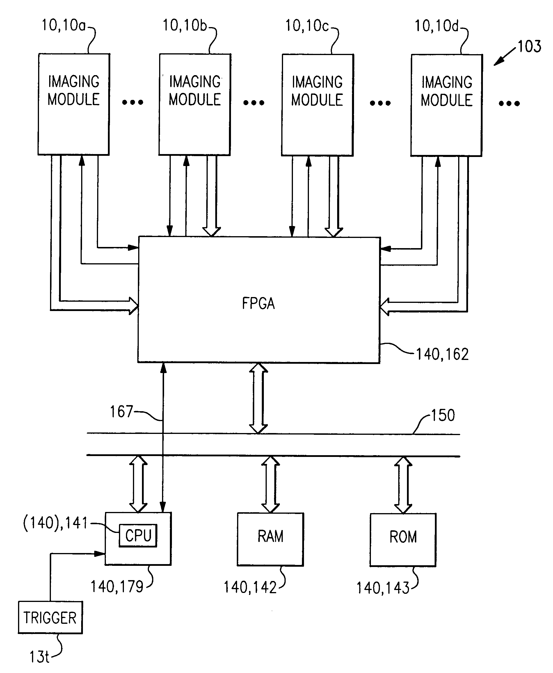
The invention is about a circuit component for an optical reader that can decode frames of image data from either a one-dimensional (1D) imaging module or a two-dimensional (2D) imaging module. The circuit component includes a microprocessor-based decoder module that decodes the frame of image data based on information about the selected imaging module and the frame of image data. The decoder module can activate at least one command to prepare for decoding the frame of image data and decodes the frame of image data accordingly. The invention also includes a computer program that performs the steps of receiving a frame of image data, determining which imaging module acquired the data, and decoding the data accordingly. The technical effect of the invention is to enable efficient and accurate decoding of frames of image data from either a 1D or 2D imaging module.

Problems solved by technology

In general, the computational power required to decode more densely encoded decodable indicia causes decoder modules suitable for such decoding to be relatively expensive as compared to decoder modules with only sufficient computational power to decode less complex decodable indicia.
A number of problems in imaging different decodable indicia arise because of the circumstances of use of the decodable indicia.
Specular reflection can result in the captured image data failing to exhibit adequate contrast between dark and light markings of a decodable indicia.
With the increased miniaturization of optical readers, light sources for illuminating a target are being positioned in closer proximity with a photodetector element of the reader, thereby rendering the modem reader more susceptible to specular reflection read failures.
The proliferation of the use of decodable markings has brought to light additional problems with presently available optical readers.
Commercially available optical readers cannot easily read high density extra wide decodable symbols or multiple symbols from a scene which are encoded in high density.

Method used


Image

  • Decoder board for an optical reader utilizing a plurality of imaging formats
  • Decoder board for an optical reader utilizing a plurality of imaging formats
  • Decoder board for an optical reader utilizing a plurality of imaging formats

Examples


first embodiment

[0167]Turning to FIG. 10a, in a first embodiment, the microprocessor-based decoder module 180 includes an audio output module 1010. An output terminal or port of the microprocessor-based decoder module 180 is connected to an input terminal or port of the audio output module 1010. The audio output module 1010 can be powered by way of the output terminal of the microprocessor-based decoder module 180, or it can be powered by an auxiliary conventional source of power (not shown) such as a power supply using a battery or a mains-connected power supply. In an exemplary embodiment, the audio output module 1010 comprises an audio codec (e.g., audio coder / decoder) 1012 connected to an output channel of the microprocessor-based decoder module 180, a D / A converter 1014 having an input terminal connected to an output terminal of the audio codec 1012, an audio amplifier 1016 having an input terminal connected to an output terminal of the D / A converter 1014, and a speaker 1018 connected to an ou...

second embodiment

[0168]In a second embodiment, shown in FIG. 10b, the microprocessor-based decoder module 180 includes an audio input module 1020. An input terminal or port of the microprocessor-based decoder module 180 is connected to an output terminal or port of the audio input module 1020. The audio input module 1020 can be powered by way of the input terminal of the microprocessor-based decoder module 180, or it can be powered by an auxiliary conventional source of power (not shown) such as a power supply using a battery or a mains-connected power supply. In an exemplary embodiment, the audio input module 1020 comprises an audio codec (e.g., audio coder / decoder) 1022 having an output terminal connected to an input channel of the microprocessor-based decoder module 180, an A / D converter 1024 having an output terminal connected to an input terminal of the audio codec 1020, an audio amplifier 1026 having an output terminal connected to an input terminal of the A / D converter 1024, and a microphone ...


PUM


Abstract

The invention relates to a microprocessor-based decoder board for an optical reader having in one embodiment a plurality of imaging modules that provide frames of image data having a plurality of formats. In one method for operating the decoder board of the invention, and a multiple imaging module reader comprising the decoder board, a frame of image data captured by a selected imaging module is decoded. The decoder board determines the format of the frame of image data from information about which of the plurality of imaging modules provided the frame of image data or from information about the frame of image data, activates as necessary a command to prepare the decoder board to decode the frame of image data according to the format provided by the imaging module, and performs the decoding.

Description

CROSS REFERENCE TO RELATED APPLICATIONS[0001]This application is related to the applications enumerated below, all of which are being filed with the United States Patent and Trademark Office contemporaneously herewith on Jan. 9, 2003, and all of which are subject to assignment to the same assignee of this application, the disclosure of each of which is incorporated herein by reference in its entirety: U.S. patent application Ser. No. 10 / 339,275, entitled “Housing for an Optical Reader;” U.S. patent application Ser. No. 10 / 339,424 (now abandoned), entitled “Optical Reader System Comprising Digital Conversion;” U.S. patent application Ser. No. 10 / 339,004 (now abandoned), entitled “Analog-to-Digital Converter with Automatic Range and Sensitivity Adjustment;” U.S. patent application Ser. No. 10 / 339,061 (now abandoned), entitled “Manufacturing Methods for a Decoder Board for an Optical Reader Utilizing a Plurality of Imaging Formats;” and U.S. patent application Ser. No. 10 / 339,281 (now ...

Claims


Application Information

Patent Timeline
Patent Type & Authority Patents(United States)
IPC IPC(8): G06K7/10
CPCG06K7/10574G06K7/1439G06K7/1098G06K7/10881
Inventor MEIER, TIMOTHY P.GARDINER, ROBERT C.HARPER, JEFFREY D.IZZO, JOHNKOZIOL, THOMAS J.LONGACRE, JR., ANDREWPETTINELLI, JOHN
Owner HAND HELD PRODS
Learn More