Multi operating electronic component
a multi-operating, electronic component technology, applied in the direction of dashboard fitting arrangement, contact mechanism, transportation and packaging, etc., can solve the problem of unfavorable increase in the height of the multi-operating electronic component including the thickness of the operating knob, and achieve the effect of reducing height and heigh
- Summary
- Abstract
- Description
- Claims
- Application Information
AI Technical Summary
Benefits of technology
Problems solved by technology
Method used
Image

Examples
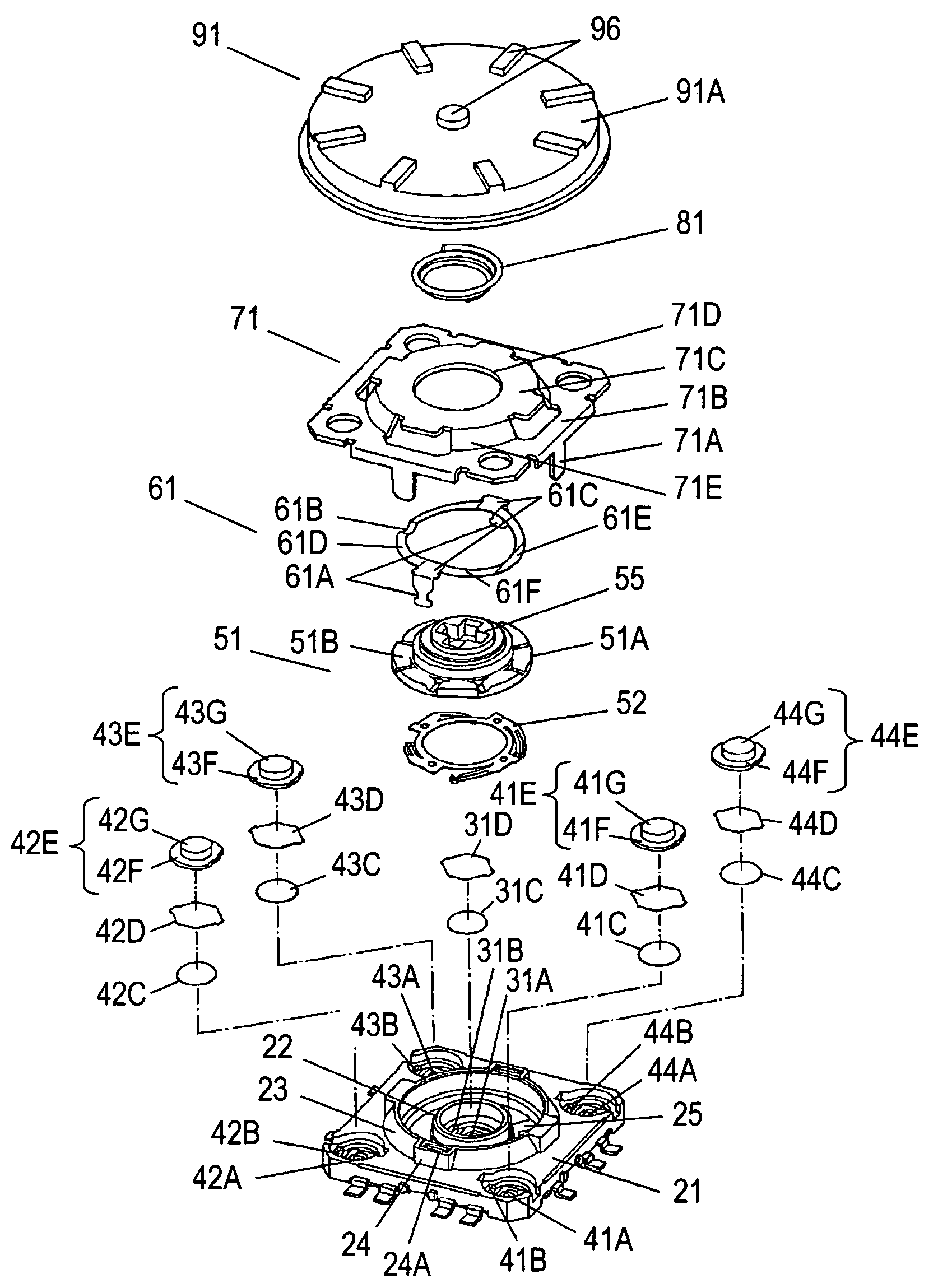
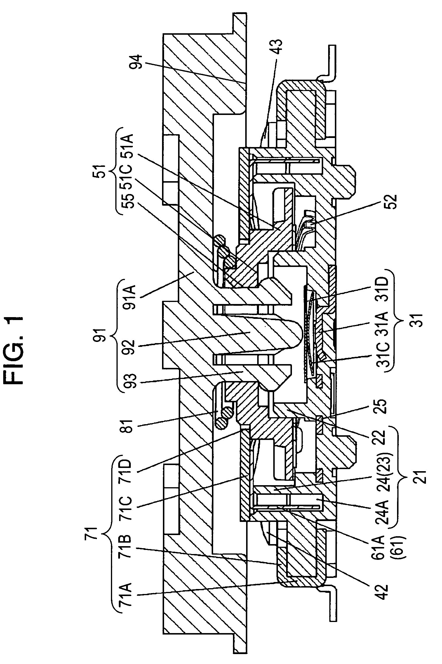
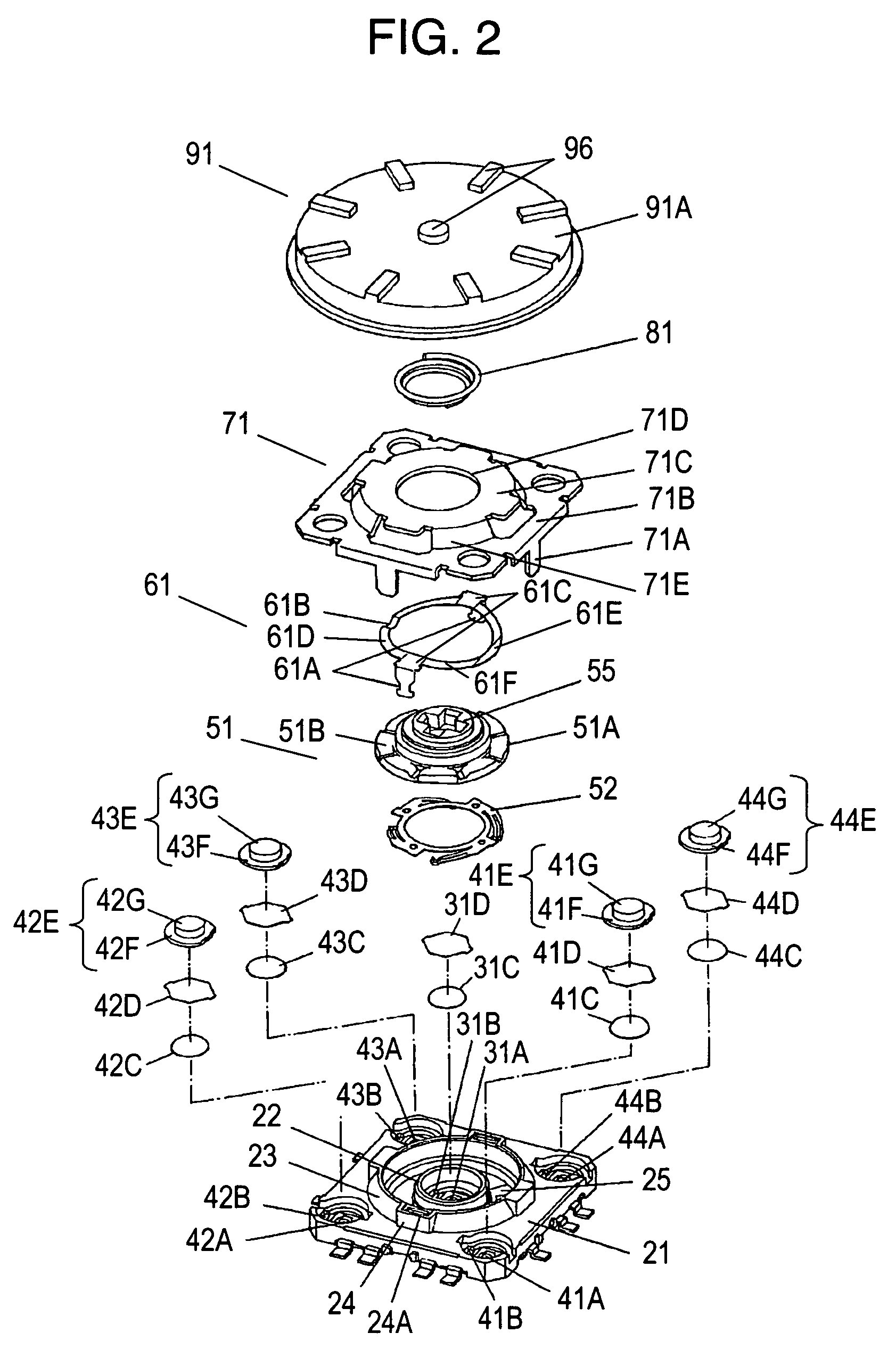
case 21
[0030]Case 21 is made of an insulating resin and has an approximately square shape. Pressing central switch (hereinafter, switch) 31 is provided at the center of case 21, and each of four pressing peripheral switches (hereinafter, switches) 41 to 44 is provided at each of the corners.
[0031]Switch 31 is composed of central contact 31A, outside contacts 31B, movable contact 31C and insulating sheet 31D. Central contact 31A and outside contacts 31B are exposed on the bottom surface of a circular recess formed in the center of case 21. Movable contact 31C is made of a metal thin plate and has a convexly domed top. Movable contact 31C is placed on outside contacts 31B so that the bottom surface of movable contact 31C is opposed to central contact 31A with a predetermined spacing therebetween. Insulating sheet 31D having flexibility is attached on the top surface around the circular recess so as to cover movable contact 31C.
[0032]On the other hand, switch 41 is composed of central contact...
PUM
 Abstract
Description
Claims
Application Information
 - R&D
- Intellectual Property
- Life Sciences
- Materials
- Tech Scout
- Unparalleled Data Quality
- Higher Quality Content
- 60% Fewer Hallucinations
Browse by: Latest US Patents, China's latest patents, Technical Efficacy Thesaurus, Application Domain, Technology Topic, Popular Technical Reports.
© 2025 PatSnap. All rights reserved.Legal|Privacy policy|Modern Slavery Act Transparency Statement|Sitemap|About US| Contact US: help@patsnap.com