Wavelength cross-connect

a cross-connecting and wavelength technology, applied in the field of alloptical switching, can solve the problems large switching cores, and difficult fabrication of large optical switching matrices

Active Publication Date: 2006-08-08
LUMENTUM OPERATIONS LLC
View PDF19 Cites 41 Cited by
  • Summary
  • Abstract
  • Description
  • Claims
  • Application Information

AI Technical Summary

Problems solved by technology

Furthermore, the cost of converting the signal from optical to electrical for switching and then back from electrical to optical becomes prohibitively expensive as the number of optical channel increases.
However, for large number of wavelengths channels per optical fibre, this leads to a very large switching core size: for example, a 50 GHz channel spacing system with 128 channels per fibre would require a 1024×1024 switching matrix to switch traffic between 8 incoming fibres to 8 outgoing fibres on a per wavelength basis.
Large optical switching matrices are hard to fabricate, complex to control, require overwhelming fibre management and are very expensive.
This huge inefficiency is the primary reason for considering a wavelength switching architecture in which the DWDM demultiplexing and multiplexing are integrated with the switching function.

Method used


Image

  • Wavelength cross-connect
  • Wavelength cross-connect
  • Wavelength cross-connect

Examples


Embodiment Construction

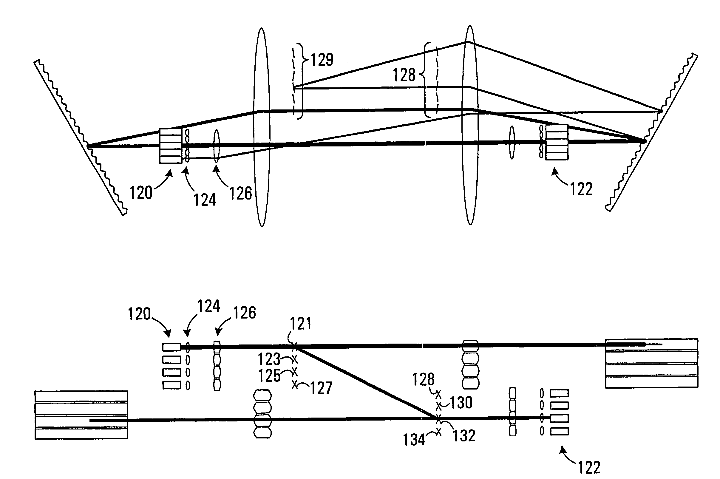
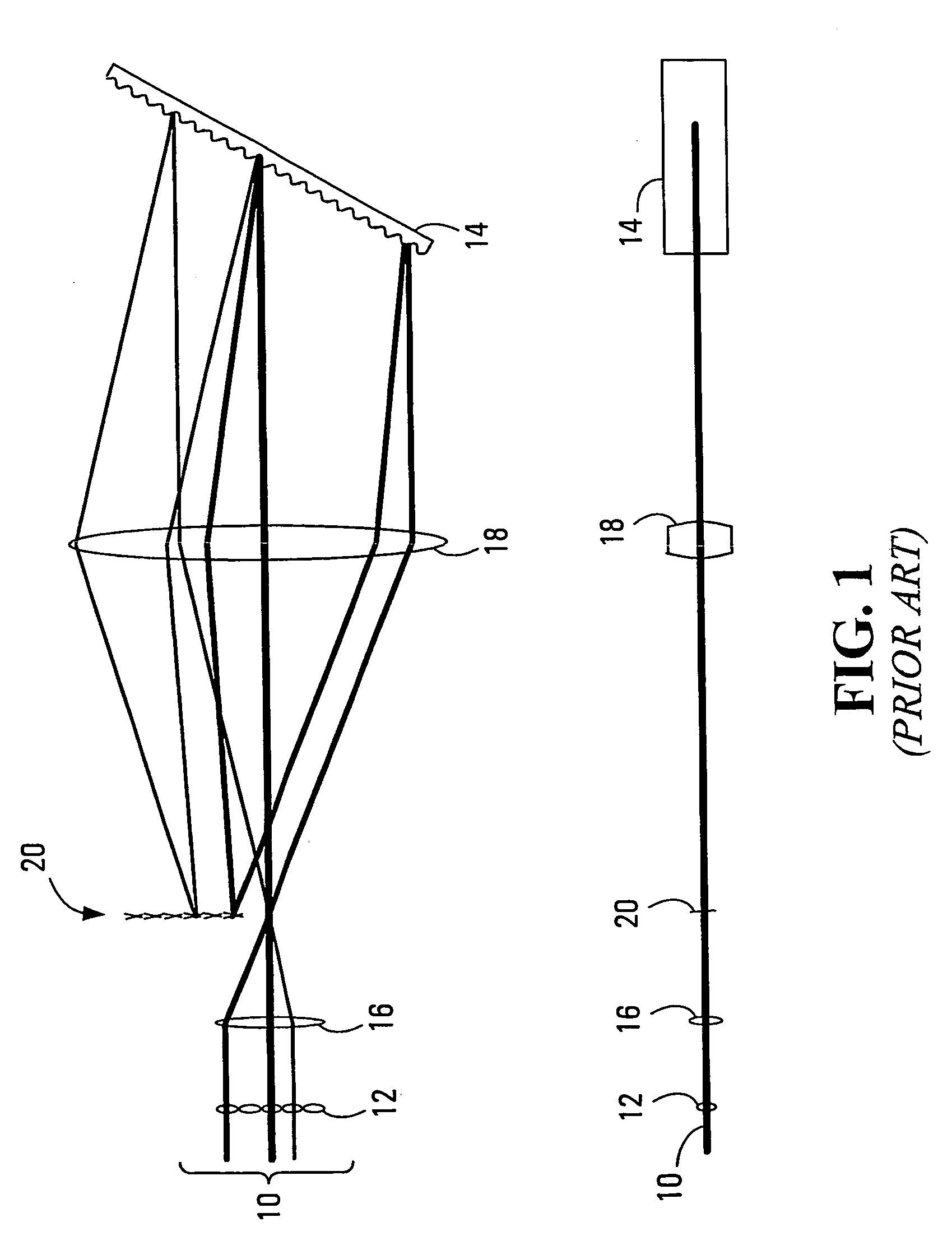
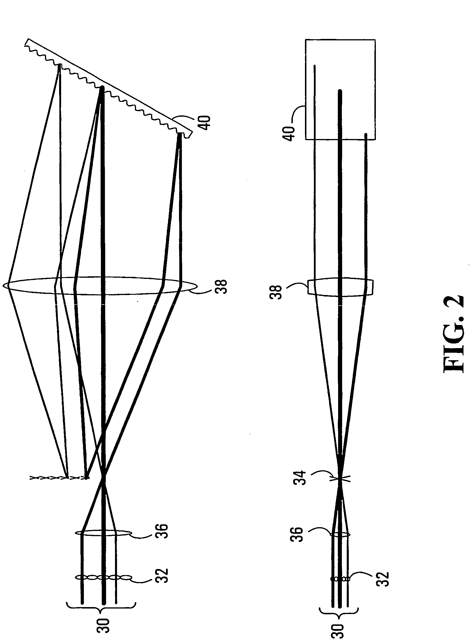
[0057]The following detailed descriptions of FIGS. 1 to 11 are used to explain the mode of operation of the invention and describe the preferred embodiments are per the invention, but should not be understood in narrow terms. Some of the elements shown can be replaced by other realizations performing similar tasks. For example, wavelength dispersion can be realized through diffraction gratings (both reflection and transmission type) or prisms in free-space embodiments or through arrayed waveguide gratings or Echelle gratings in waveguide embodiments. Bulk optical elements having optical powers can be any of a lens, a curved mirror, or any suitable combination of optical elements, either spherical or cylindrical, that provide the appropriate optical function. The array of switching means can be either reflective (mirrors, tunable gratings, interferometric arrangements of fixed and movable membranes, etc.), with the best mode being micro-mirror arrays fabricated through micro-fabricat...


PUM


Abstract

A wavelength cross connect is provided in which wavelength channels are individually switchable from one of a first set of ports to one of a second set of ports. Add and drop capability is provided on the sets of ports. Some embodiments feature a single row of ports, while others feature two dimensional arrays of ports. Some embodiments employ one dispersive element per port, and others employ one dispersive element per row of ports. Embodiments featuring transmissive and non-transmissive switching elements are provided.

Description

This application claims the benefit of U.S. Provisional Application No. 60 / 381,376 filed on May 20, 2002.FIELD OF THE INVENTION[0001]This invention relates to the field of DWDM fiber optics telecommunications and in particular to the field of all-optical switching.BACKGROUND OF THE INVENTION[0002]The advent of DWDM fibre optics telecommunications systems in the early 1990s have enabled a dramatic increase in the transmission capacity over point-to-point links. This was achieved through multiplexing of a large number of individually modulated light beams of different wavelengths onto the same optical fibre. Typical systems installed today would have 64 or more independent channels precisely aligned onto an ITU-T standardized grid at 100 GHz, 50 GHz or even narrower channel spacing. With routine modulation speeds of 10 Gb / s and attaining 40 Gb / s in laboratory experiments, it is not unusual to obtain aggregated capacities in the order of several terabits per second of information being...

Claims


Application Information

Patent Timeline
Patent Type & Authority Patents(United States)
IPC IPC(8): G02B6/26G02B6/34G02B6/35H04J14/02H04Q11/00
CPCG02B6/12011G02B6/12033G02B6/2931G02B6/29311G02B6/29313G02B6/356H04Q11/0005G02B6/12019H04Q2011/0032G02B6/29382G02B6/3512G02B6/3526G02B6/3528G02B6/3534H04J14/0212H04Q2011/0016H04Q2011/0026H04Q2011/003
Inventor DUCELLIER, THOMASHNATIW, ALAN
Owner LUMENTUM OPERATIONS LLC
Why Eureka
Try Eureka