
Method of operating a crossbar switch

a crossbar switch and switch technology, applied in the direction of instruments, electric digital data processing, etc., can solve the problems of inconvenient link list buffer mechanism and too much time for traversing the linked list buffer, so as to avoid performance loss

Inactive Publication Date: 2006-08-08
INT BUSINESS MASCH CORP
View PDF13 Cites 76 Cited by
  • Summary
  • Abstract
  • Description
  • Claims
  • Application Information

AI Technical Summary

Benefits of technology

[0015]Accordingly, it is an object of the present invention to provide an improved method of operating a crossbar switch which requires fewer buffer memory within a crossbar switch while at the same time supporting multiple priority levels and a link paralleling mode.
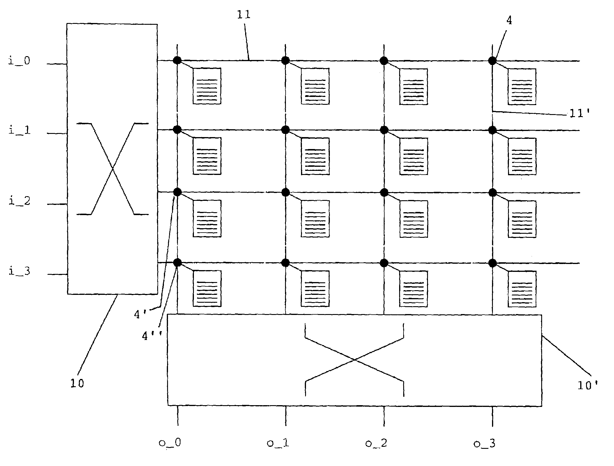
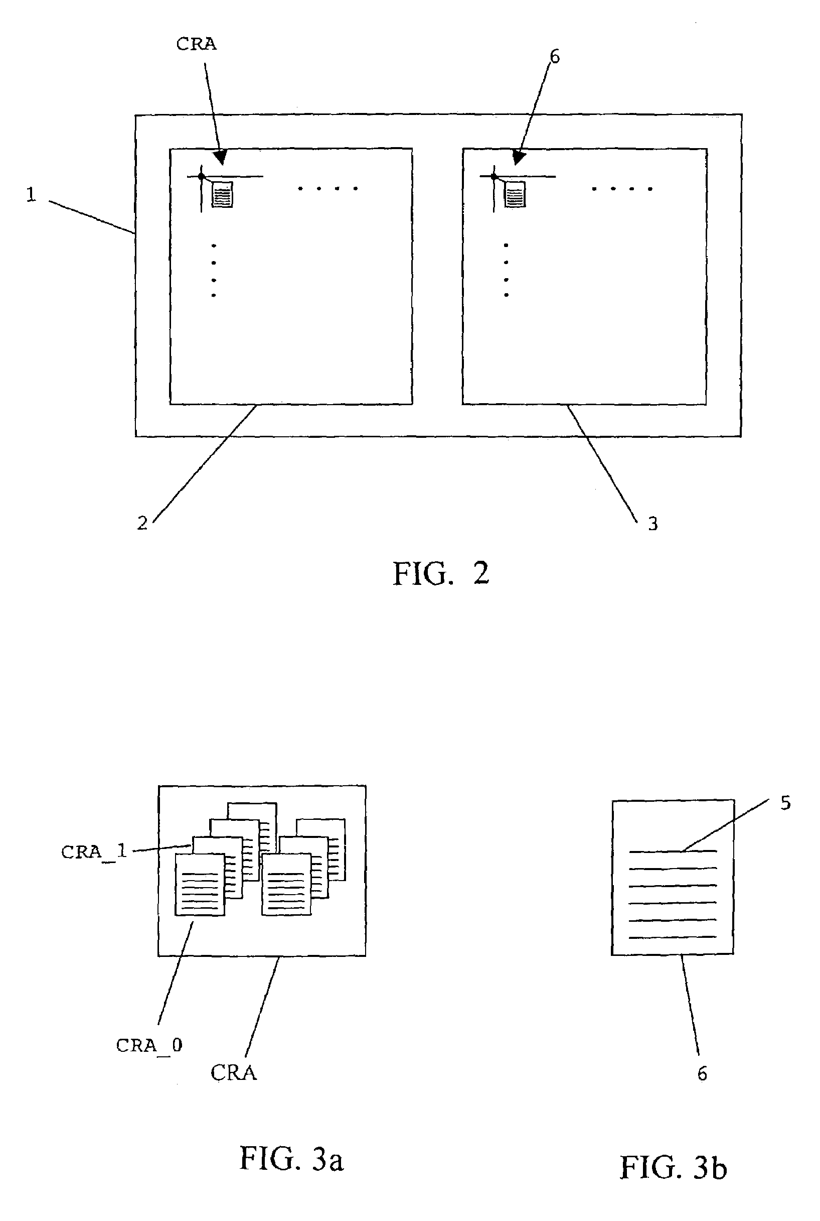
[0016]According to the present invention, this object is achieved by providing for each crosspoint a pool of buffers within said control logic and by temporarily storing address information related to said information packets in said pool of buffers. The main advantage of said pool of buffers is the flexibility of storing said address information. Whenever a packet arrives at an input port of the crossbar switch, it is stored in a buffer being member of said pool of buffers. If said packet is the first packet with a certain priority level, a new, empty buffer is taken from the pool and is reserved for packets of said priority level. Following incoming packets will also be written to said buffer, provided the have the same priority level as well.

Problems solved by technology

The linked list buffer mechanism is not favorable since it only allows to read one address entry per cycle which for example is not sufficient for link paralleling.
Especially in case of different priorities, traversing the linked list buffer takes too much time.

Method used


Image

  • Method of operating a crossbar switch
  • Method of operating a crossbar switch
  • Method of operating a crossbar switch

Examples


Embodiment Construction

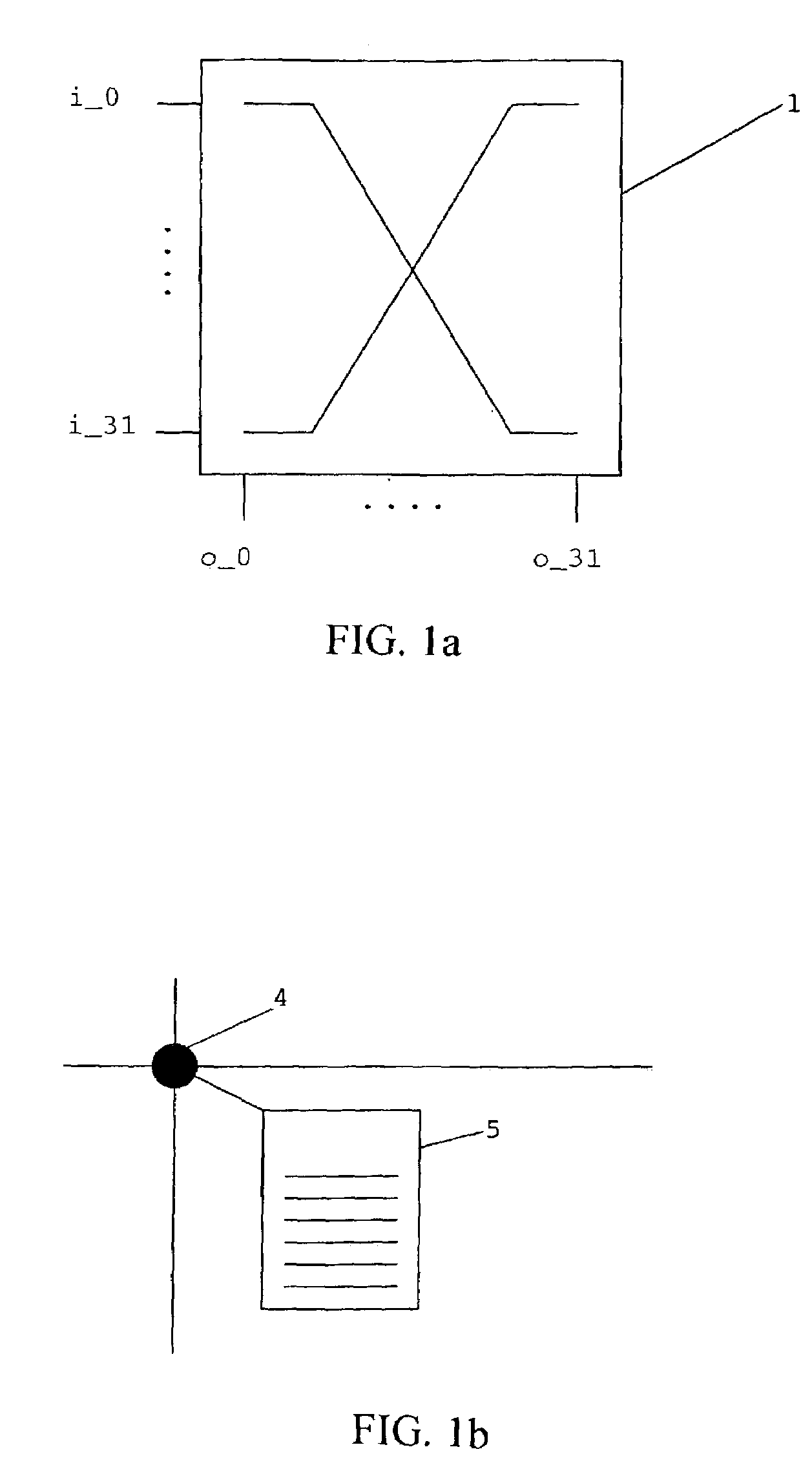
[0055]The crossbar switch 1 schematically depicted in FIG. 1a comprises 32 input ports i_0, . . . , i_31 and 32 output ports o_0, . . . , o_31. It is capable of routing information packets incoming at an arbitrary input port to one of said output ports o_0, . . . , o_31.

[0056]Crossbar switch 1 has a plurality of input crossbars (not shown), each of which is connected to one of the input ports i_0, . . . , i_31. Further, crossbar switch 1 has a plurality of output crossbars, each of which is connected to one of the output ports o_0, . . . , o_31.

[0057]An intersection of an input crossbar with an output crossbar is called crosspoint 4. A crosspoint 4 represents the physical connection of an input port and an output port via the corresponding input / output crossbars and is schematically shown in FIG. 1b.

[0058]As can be seen from FIG. 1b, a buffer comprising a plurality of buffer entries 5 is assigned to said crosspoint. The buffer is usually employed for temporarily storing information...


PUM


Abstract

The present invention relates to a method of operating a crossbar switch (1) having a control logic (2) and n input ports (i—0, . . . , i_n-1) and m output ports (o—0, . . . , o_m-1), wherein information packets of p different priority levels are routed from said n input ports (i—0, . . . , i_n-1) to said m output ports (o—0, . . . , o_m-1). Within said control logic (2), a pool (CRA) of buffers (CRA—0, CRA—1, . . . ) is provided for each crosspoint (4) for temporarily storing address information related to said information packets.

Description

BACKGROUND OF THE INVENTION:[0001]The present invention relates to crossbar switches, and in particular to a method of operating a crossbar switch having a control logic and n input ports and m output ports, wherein information packets of p different priority levels are routed from said n input ports to said m output ports.[0002]The present invention further relates to a crossbar switch having a control logic and n input ports and m output ports wherein information packets of p different priority levels are routed from said n input ports to said m output ports.[0003]Additionally, the present invention relates to a networking system with at least one crossbar switch.[0004]Crossbar switches are used in high performance computer systems and nodes of electronic networks such as communication networks to route an information packet arriving at an arbitrary input port to a specified output port.[0005]A crossbar switch comprises n input crossbars each of which is assigned to one of said n ...

Claims


Application Information

Patent Timeline
Patent Type & Authority Patents(United States)
IPC IPC(8): G06F13/00G06F13/40
CPCG06F13/4022
Inventor CEBULLA, MARKUSGOLDRIAN, GOTTFRIED ANDREASLEPPLA, BERNDSCHUMACHER, NORBERT
Owner INT BUSINESS MASCH CORP
Learn More