Opto-electronic distributed crossbar switch

a crossbar switch and distributed technology, applied in multiplex communication, optical elements, instruments, etc., can solve the problems of limited digital signals, affecting system performance, and limiting capacitive effects

Inactive Publication Date: 2003-07-22
RAYTHEON CO
View PDF2 Cites 71 Cited by
  • Summary
  • Abstract
  • Description
  • Claims
  • Application Information

AI Technical Summary

Problems solved by technology

However, these systems are hampered by capacitive effects and distance limitations and are typically limited to digital signals.
Prior optical crossbar switching systems have been also been limited to digital signals.
However, hybrid crossbar switching systems require a large number of connectors.
Further, historically, these connectors have been found to be somewhat unreliable.

Method used


Image

  • Opto-electronic distributed crossbar switch
  • Opto-electronic distributed crossbar switch
  • Opto-electronic distributed crossbar switch

Examples


Embodiment Construction

Illustrative embodiments and exemplary applications will now be described with reference to the accompanying drawings to disclose the advantageous teachings of the present invention.

While the present invention is described herein with reference to illustrative embodiments for particular applications, it should be understood that the invention is not limited thereto. Those having ordinary skill in the art and access to the teachings provided herein will recognize additional modifications, applications, and embodiments within the scope thereof and additional fields in which the present invention would be of significant utility.

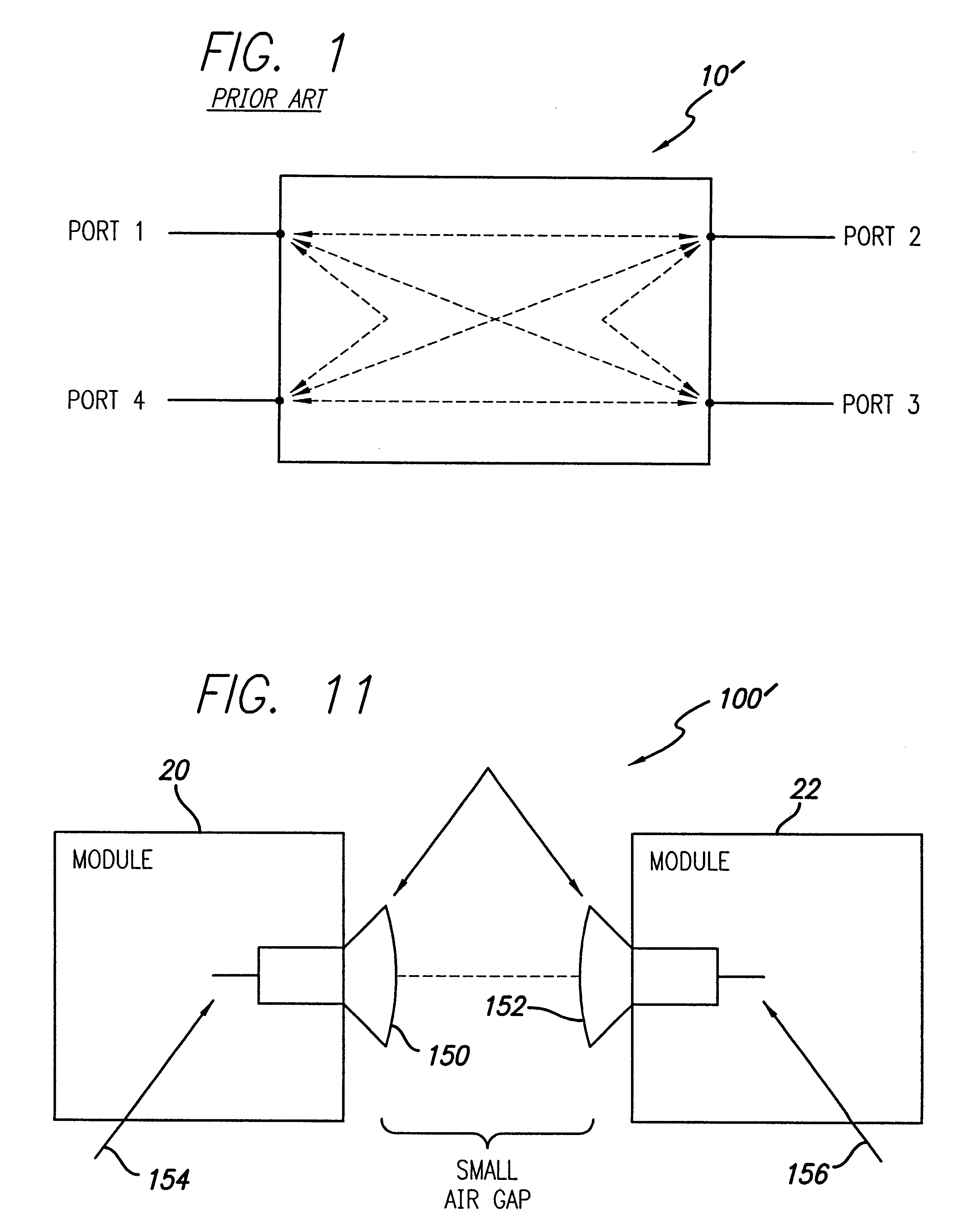
FIG. 1 is a diagram showing a typical 4.times.4 crossbar switch. The generic crossbar switch 10' allows an incoming signal to a switch port to be directed (switched) to any other output port. In the example, the switch 10' has the capability to have any one of four input ports routed to any or all of the other 3 output ports for both transmission and reception a...


PUM


Abstract

The invention is an optoelectronic (OE) crossbar switch (10) for both digital and analog signals, used either separately or combined, whose functions are reconfigurable and distributed. The invention allows multiple senders to be connected with multiple receivers simultaneously. The invention uses optical filters for wavelength division multiplexing and demultiplexing (WDM and WDD). A single fiber module input / output port carries multiple bi-directional signals that are optically filtered out in the module using WDM / WDD filters (12) at each sender / receiver and then selected after optical filtering using photodiode detectors (15) as detectors and switches. Laser transmitters (14), photodiode detectors (15), and smart electronics (18) are used to implement the crossbar switch functions. In addition to optical filters, the use of time division multiplexing (TDM) and code division multiple access (CDMA) implemented either electrically or optically are taught to increase the number of independent users that the distributed switch handles. The switch can be cascaded with other switches using optical bridging circuits (100) to create a scaleable interconnect fabric. An arbitration technique can be used which allows signals to be sent only when the intended receiver is capable of accepting these signals.

Description

1. Field of the InventionThe present invention relates to switching systems and methodologies. More specifically, the present invention relates to optical and electronic crossbar switching circuits, systems and techniques.2. Description of the Related ArtA generic crossbar switch allows an incoming signal to a switch port to be directed (switched) to any other port. Crossbar switches are used in radar and numerous other applications to distribute radio frequency and / or digital signals from one source (e.g., an antenna) to multiple destinations (e.g., processors) and vice versa. Previously, crossbar switching was implemented electronically. However, these systems are hampered by capacitive effects and distance limitations and are typically limited to digital signals. Prior optical crossbar switching systems have been also been limited to digital signals.Hybrid arrangements use a combination of electronic and optical switching elements. However, hybrid crossbar switching systems requi...

Claims


Application Information

Patent Timeline
Patent Type & Authority Patents(United States)
IPC IPC(8): G02B6/43H04Q11/00G02B6/42
CPCG02B6/43H04Q11/0005G02B6/4214H04Q2011/0016H04Q2011/0032H04Q2011/0058
Inventor NEWBERG, IRWIN L.MELLEMA, DWIGHT J.
Owner RAYTHEON CO
Why Eureka
Try Eureka