
High bandwidth reconfigurable on-chip network for reconfigurable systems

a reconfigurable system and high bandwidth technology, applied in the field of reconfigurable systems, can solve the problems of reducing wiring resources, communication speed is limited, and large amount of wiring resources required for crossbar switches is typically a disadvantag

Active Publication Date: 2007-05-29
XILINX INC
View PDF4 Cites 78 Cited by
  • Summary
  • Abstract
  • Description
  • Claims
  • Application Information

AI Technical Summary

Benefits of technology

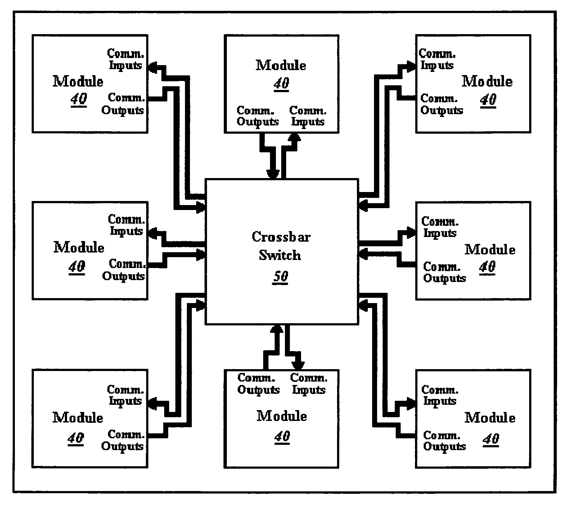
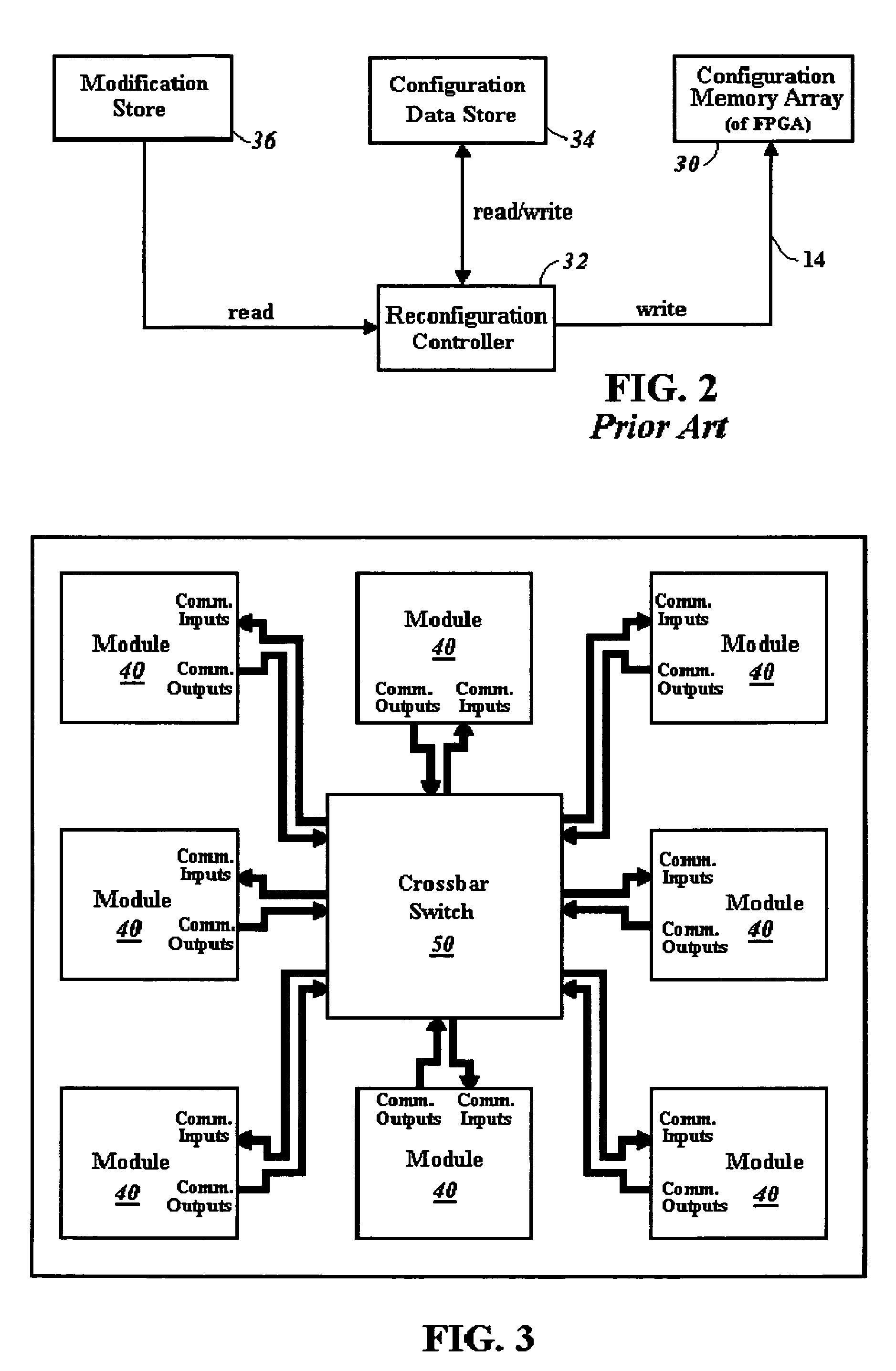
[0016]The crossbar switch is presented as an on-chip communications network for reconfigurable task based systems. A large amount of wiring resources required for a crossbar switch is typically a disadvantage in network systems, and buses or packet type systems were typically implemented to reduce the wiring necessary. The reduction in wiring resources are, however, obtained with an undesirable increase the amount of time for access to the network for communication. However, a reconfigurable system such as an FPGA has a significant amount of wiring resources readily available. The crossbar switch in one embodiment, labeled as a “partial connection crossbar,” provides a separate connection from a module output to each module input. The crossbar switch can be easily updated, or reconfigured by a processor acting as a reconfiguration controller. Unlike packet networks and bus-based networks, a crossbar switch allows each module to independently communicate with other modules.
[0017]The crossbar switch can be implemented in CLBs in one of several different embodiments. In a first embodiment, a wide crossbar switch is created with CLB input multiplexers (IMUXs) linked to provide a separate channel for each communication path. For a wide crossbar switch providing a connection from every output to every input with a system having 928 module outputs and 928 module inputs, 4,836 CLBs are used. In a second embodiment, a Clos type crossbar switch is implemented reducing the number of CLBs required for a 928×928 system to 1,324 CLBs. In a third embodiment, the partial connection crossbar configuration is used to reduce CLBs required for a 1 024×1 024 crossbar switch to 256 CLBs. The partial connection crossbar is used for communication signals between modules, where data is typically sent in bytes of data at a time, so for example a Bit 0 output will only go to a Bit 0 input and not to other inputs such as Bit 1 or 2.
[0020]Partial reconfiguration processes are contemplated for use to rapidly reconfigure both the modules and the crossbar switch used for communications according to the present invention. The crossbar switch is updated through reconfiguration at the same time that tasks are reconfigured into a module or moved between modules. During partial reconfiguration, tasks performed by the modules and the communications crossbar switch that are not being changed can continue operation.

Problems solved by technology

Although the network enables high bandwidth communication, communication speed is limited because the module tasks share access to a common network.
A large amount of wiring resources required for a crossbar switch is typically a disadvantage in network systems, and buses or packet type systems were typically implemented to reduce the wiring necessary.
The reduction in wiring resources are, however, obtained with an undesirable increase the amount of time for access to the network for communication.
The auto router typically will not be able to perform wire-by-wire routing as the API can do.

Method used


Image

  • High bandwidth reconfigurable on-chip network for reconfigurable systems
  • High bandwidth reconfigurable on-chip network for reconfigurable systems
  • High bandwidth reconfigurable on-chip network for reconfigurable systems

Examples


Embodiment Construction

[0034]FIG. 3 illustrates a reconfigurable on chip network in accordance with an embodiment of the present invention. The on chip network can be implemented with a programmable logic device (PLD), for example an FPGA or, in an another example, a complex programmable logic device (CPLD). The structure includes a number of modules 40 having communication outputs connected through a crossbar switch 50 to communication inputs of other ones of the modules 40. In one embodiment, each module communication output is connected through the crossbar switch 50 to a corresponding communication input on a separate line in the “partial connection crossbar switch” configuration. The crossbar switch 50 is programmed into the reconfigurable chip logic, along with the modules 40. As the modules 40 have tasks they are implementing modified by reconfiguring the PLD, the crossbar switch 50 can likewise be reconfigured to link any module communication output and inputs that change.

[0035]Crossbar switches a...


PUM


Abstract

A crossbar switch (50) is implemented in a reconfigurable circuit, such as a FPGA, instantiated with a number of modules (40), the crossbar switch (50) providing communication links between the modules (40). The modules (40) and crossbar switch (50) can be easily updated in a partial reconfiguration process changing only portions of modules (40) and the crossbar switch (50) while other portions remain active. The crossbar switch (50) uses individual wiring to independently connect module outputs and inputs so that asynchronous communications can be used. The crossbar switch (50) can be implemented in different embodiments including a Clos crossbar switch, and a crossbar switch connecting each module output only to a corresponding module input, allowing for a reduction in the amount of FPGA resources required to create the crossbar switches.

Description

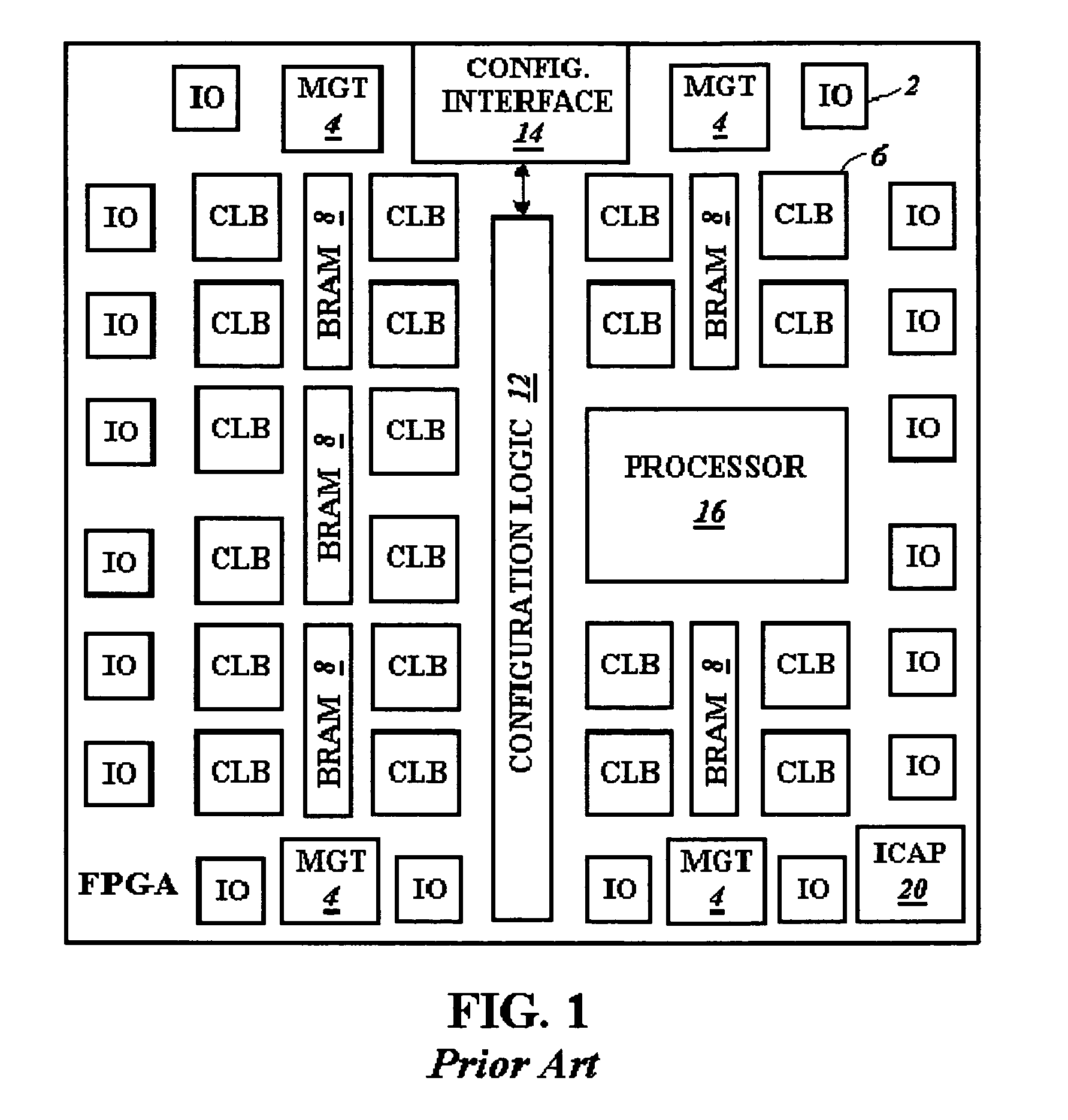
BACKGROUND[0001]1. Technical Field[0002]The present invention relates to a reconfigurable system, such as a programmable logic device, configured to provide communication between different modules.[0003]2. Related Art[0004]Reconfigurable systems, such as FPGAs, have traditionally been used as off-the-shelf replacements for Application Specific Integrated Circuits (ASICs), or as customizable versions of Application Specific Standard Products (ASSPs). As opposed to ASICs or ASSPs, programmability enables FPGAs to be purchased by customers and configured to provide a desired circuit. The FPGAs are further reconfigurable allowing reprogramming after startup. Reconfigurability allows FPGAs, for example, to be used for software-defined radios that have circuitry controlling their frequencies updated as the radio location changes. As another example, decryption algorithms have their keys and decoding circuits updated over time.[0005]A block diagram of components of a conventional FPGA is s...

Claims


Application Information

Patent Timeline
IPC IPC(8): H01L25/00H03K19/177
CPCH03K19/17736H03K19/17752H03K19/17756
Inventor LEVI, DELONBECKER, TOBIAS J.
Owner XILINX INC
Learn More