Portable filter unit and methods for using same

a filter unit and portable technology, applied in the field of portable filters, can solve the problems of noxious fume entering the building, illness and disruption, filter configuration, etc., and achieve the effect of preventing the spread of contamination

Inactive Publication Date: 2005-12-27
LAITI PETER J
View PDF15 Cites 27 Cited by
  • Summary
  • Abstract
  • Description
  • Claims
  • Application Information

AI Technical Summary

Benefits of technology

[0007]The present invention relates to a portable filter unit having a fan section and a filter section, each mounted on their own respective movable carts, in which the fan section and filter section are adapted for attachable / detachable interconnection with each other at either of their respective lateral ends. This permits provision of either blow through or draw through of air through the filter section of the filter unit such that the fan section can be positioned on an air flow side of the filter section appropriate for a given threat scenario insofar. Namely, the fan section can be located upstream or downstream of the filter section effective to as prevent the spread of contamination between outside and inside environments otherwise possible due to contaminated air leaking into or infiltrating into the fan section and being passed unfiltered into clean air space or outside environment.
[0008]The capability to rapidly reconfigure the filter and fan sections of the filter unit of the present invention makes it possible to operate the filter unit under a wide variety of CBR or other toxic / bacterial / viral contamination scenarios while making the unit tolerant of air leakage from or infiltration into the filter unit and without the need to try to incorporate highly elaborate or expensive air sealing measures on the multi-sectioned filter unit to combat the leakage / infiltration problem.

Problems solved by technology

Every year there are numerous incidents of noxious fumes entering buildings and causing illness and disruptions due to accidents, deliberate attacks or malicious pranks.
That filter configuration, however, would have serious drawbacks if implemented as a general airspace cleaner used to clean and pressurize an enclosure when this unit is located in the contaminated area.
Although not recognized or address in the prior art, in that general airspace cleaning scenario, air leakage or infiltration would occur, or would be at high risk of occurring, in the intervening air passage or at the associated air seals that structurally must be made between the filtering and fan assemblies or around filter service doors panels that are required of such a filter unit.
Air infiltration into that filter unit could occur when the fan assembly is being used to draw or pull air through the filter unit due to contaminated air present in the surrounding airspace bypassing the filter assembly by infiltrating through the air sealed connection or duct between the filter and fan assemblies.
In this manner, contaminated unfiltered air can get sucked into and combine with the filtered air stream.
In that undesired infiltration situation, the actual or potential problem is that filtered air can become recontaminated by the contaminated infiltrating air before it is discharged from the filter unit.
The prior art does not mention or address this application or problems arising therein.
If an attempt were made to design the leakage or infiltration problem away, i.e., attempt to manufacture a bona fide completely air-tight filter unit enclosure, that generally would be too costly for filter units intended for wide market distribution including private consumers.

Method used


Image

  • Portable filter unit and methods for using same
  • Portable filter unit and methods for using same
  • Portable filter unit and methods for using same

Examples


Embodiment Construction

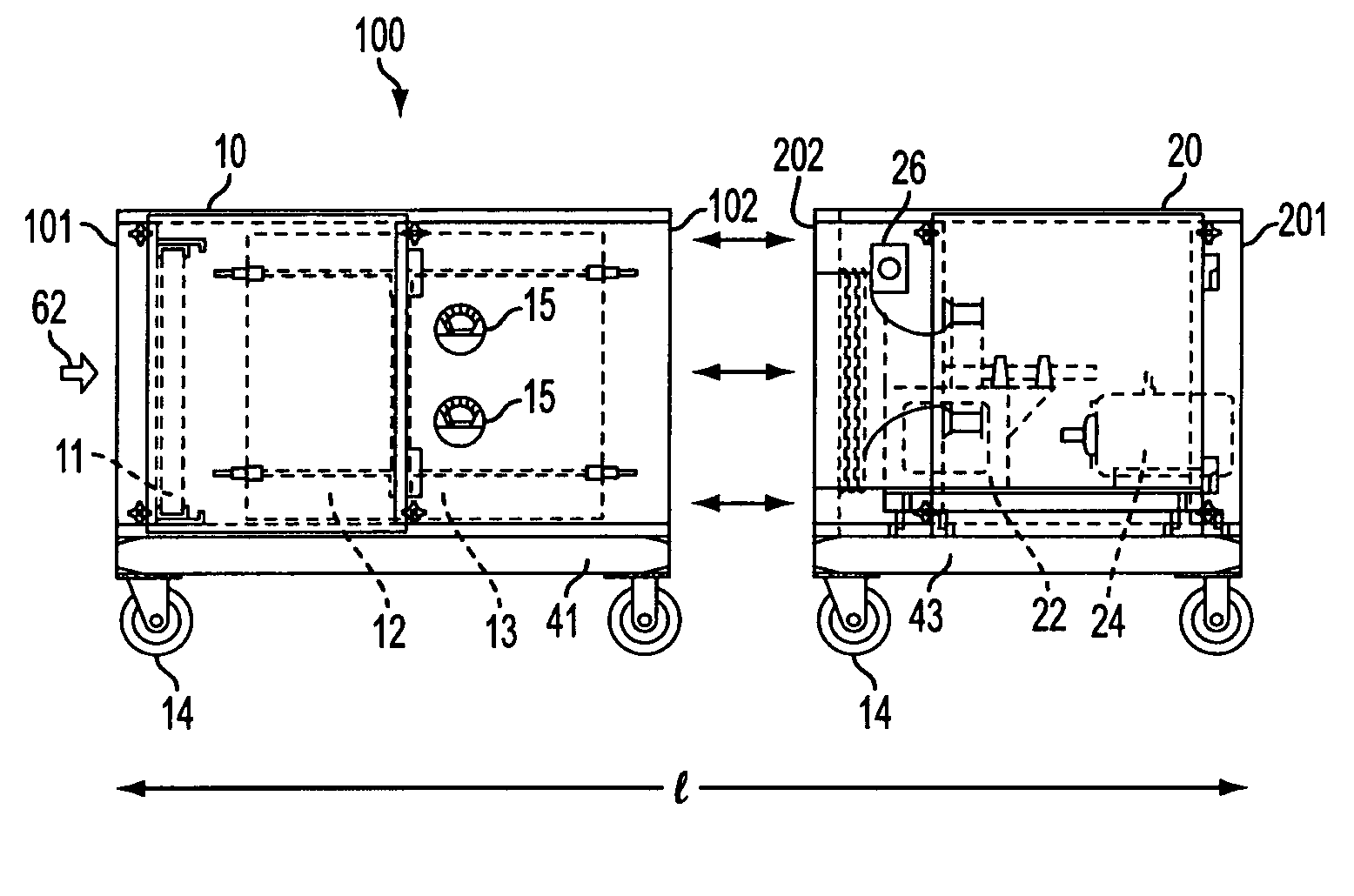
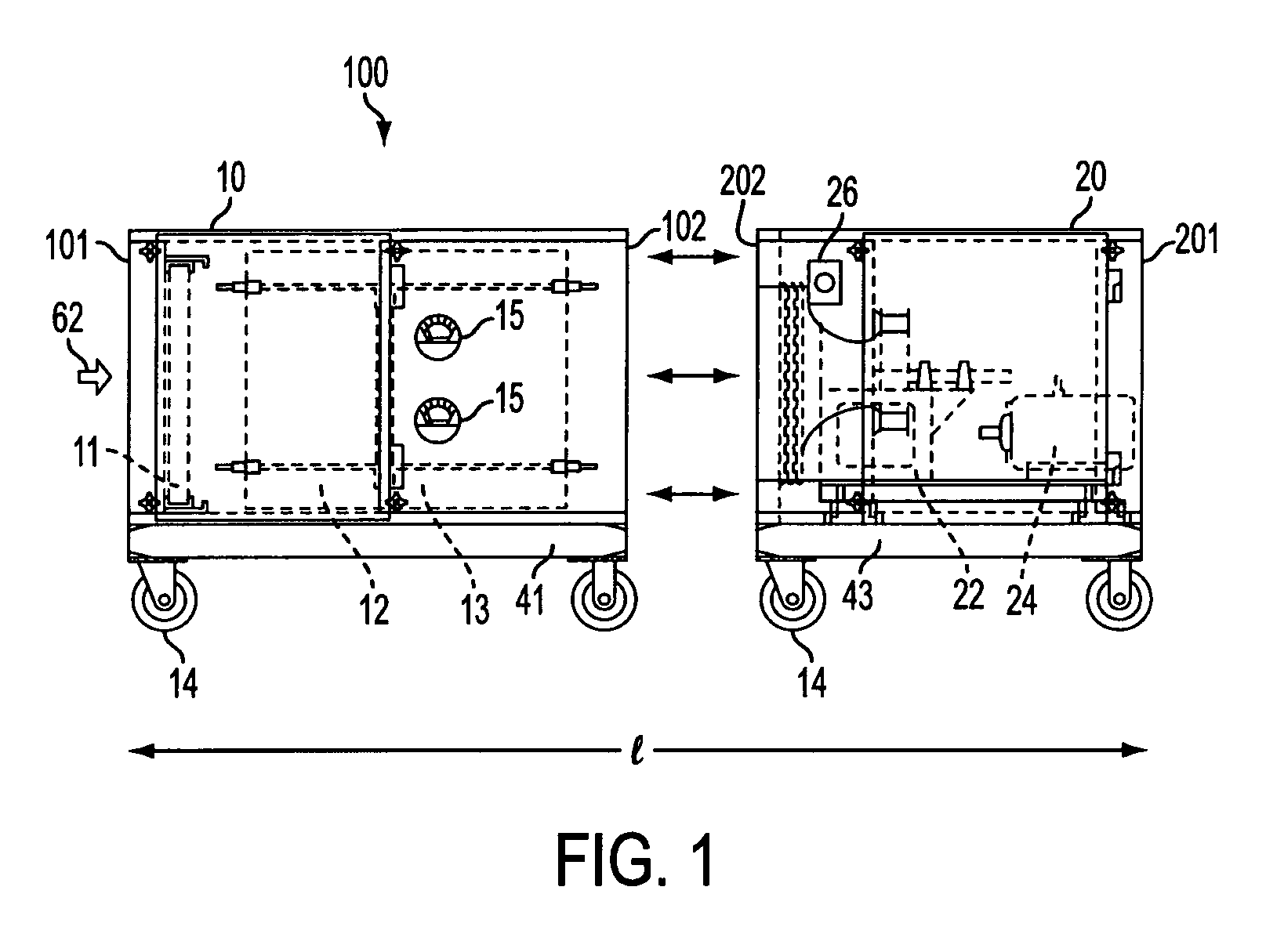
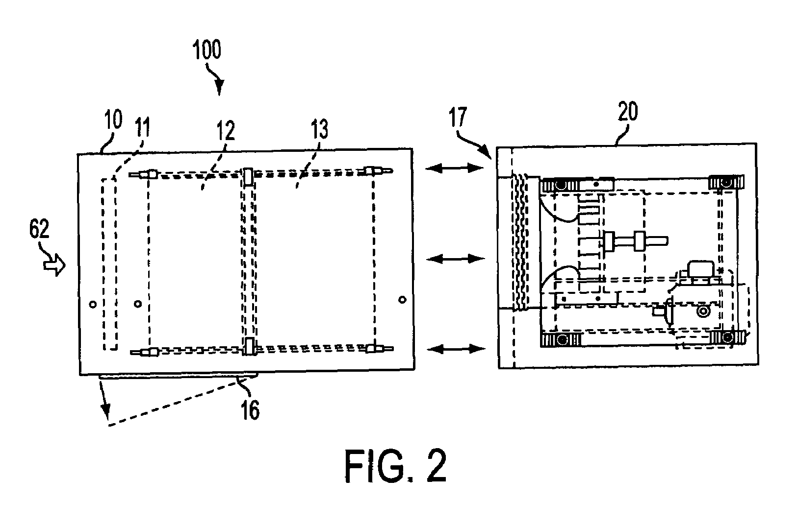
[0024]The present invention provides a filter unit adapted to permit reconfiguration of separate, releasably attachable filter and fan sections thereof to accommodate numerous different contamination scenarios, such that any leakage of contaminated air from the filter unit or infiltration of outside contaminated air into the fan section or fluid passage established between the attached filter and fan sections that passes unfiltered into an environment creates no increased risk of CBR exposure to persons inside and outside the enclosure.

[0025]The sequence of the respective filter and fan sections of the portable filter unit can be readily changed using integral quick-release releasable fasteners so that the filter unit can be operated in air pull through-or air blow through modes as appropriate to avoid contamination problems in a wide variety of implementation scenarios. The filter unit of the present invention is particularly applicable to filtering chemical, biological and radiolo...


PUM

PropertyMeasurementUnit
sizeaaaaaaaaaa
sizeaaaaaaaaaa
sizeaaaaaaaaaa

Abstract

Portable, rapidly deployable filter unit for use in air filtering methods providing high efficiency filtration of airborne toxins. The filter unit includes a fan section and a filter section that are releasably attachable at their respective lateral ends permitting the filter unit to be reconfigurable to properly handle a variety of threat scenarios involving protecting the occupant(s) and equipment in an enclosure against an airborne release of toxic chemical, biological, or radiological agents that threaten to contaminate the air supply, or, alternatively, for decontaminating the air of an isolation room occupied by contaminated or contagiously ill persons or materials and protecting the occupants or equipment located outside the isolation room.

Description

TECHNICAL FIELD[0001]The present invention relates generally to a portable, rapidly deployable filter unit for use in air filtering methods providing high efficiency filtration of airborne toxins. More particularly, it relates to a filter unit including fan section and a filter section that are releasable and attachable at their respective lateral ends permitting the filter unit to be reconfigurable to properly handle a variety of threat scenarios involving protecting the occupant(s) or equipment in an enclosure against external airborne release of toxic chemical, biological, or radiological agents that threaten to contaminate the air supply (a positive air pressure situation), or, alternatively, for decontaminating the air of an isolation room occupied by toxically contaminated or contagiously ill persons (a negative air pressure situation). In either scenario the filter unit will / can be located in a contaminated or non-contaminated area. The location of the filter unit will dictat...

Claims


Application Information

Patent Timeline
Patent Type & Authority Patents(United States)
IPC IPC(8): A62B11/00F24F7/003B01D46/00B01D46/42B01D53/02F24F8/108F24F8/158
CPCB01D46/0023B01D46/0036B01D46/0091B01D46/0097B01D53/02F24F3/1603A62B11/00B01D2271/02B01D2273/30F24F2003/1625F24F2221/12F24F2221/44Y10S55/18F24F8/158F24F8/10B01D46/62F24F8/108F24F7/003
Inventor LAITI, PETER J.
Owner LAITI PETER J
Why Eureka
Try Eureka