Shaft of a tool or the like

a technology of a tool shaft and a shaft, applied in the direction of rod connections, wing knobs, furniture parts, etc., can solve the problems of rusting of metal parts of the spring pin arrangement, inability to hold the tool shaft in place sufficiently tightly, and inability to adjust the mechanism based on friction, etc., to achieve the effect of convenient managemen

Inactive Publication Date: 2006-08-15
FISKARS CONSUMER
View PDF22 Cites 14 Cited by
  • Summary
  • Abstract
  • Description
  • Claims
  • Application Information

AI Technical Summary

Benefits of technology

[0006]The problems described above are solvable by a tool shaft whose length is adjustable and which comprises a first shaft section and a second shaft section, which are attached to each other by adjusting means and which move telescopically with respect to each other when the shaft length is adjusted. The adjusting means for adjusting the shaft length comprise a sleeve provided in the first shaft section and an at least partly toothed spindle provided in the second shaft section, the first end of the spindle being taken through the sleeve. The sleeve and the spindle attach the first and the second shaft section adjustably to each other so that the sleeve and the spindle can be turned with respect to each other into a position where the adjustment of the shaft length is prevented and into a position allowing the adjustment of the shaft length where the spindle can move in the sleeve in the longitudinal direction.
[0008]An advantage of the system according to the invention is that the locking of the tool adjusting mechanism does not loosen during use, it is easily manageable by the user and the mechanism does not require metal parts, which may rust outside, but it can be made completely of plastic, for example.

Problems solved by technology

A problem associated with the solutions described above is that adjusting mechanisms based on friction cannot usually hold the tool shaft in place sufficiently tightly during use or they loosen during use.
Furthermore, such tools are often stored outside, and therefore the metal parts of the spring pin arrangement may rust and become useless.

Method used


Image

  • Shaft of a tool or the like
  • Shaft of a tool or the like
  • Shaft of a tool or the like

Examples


Embodiment Construction

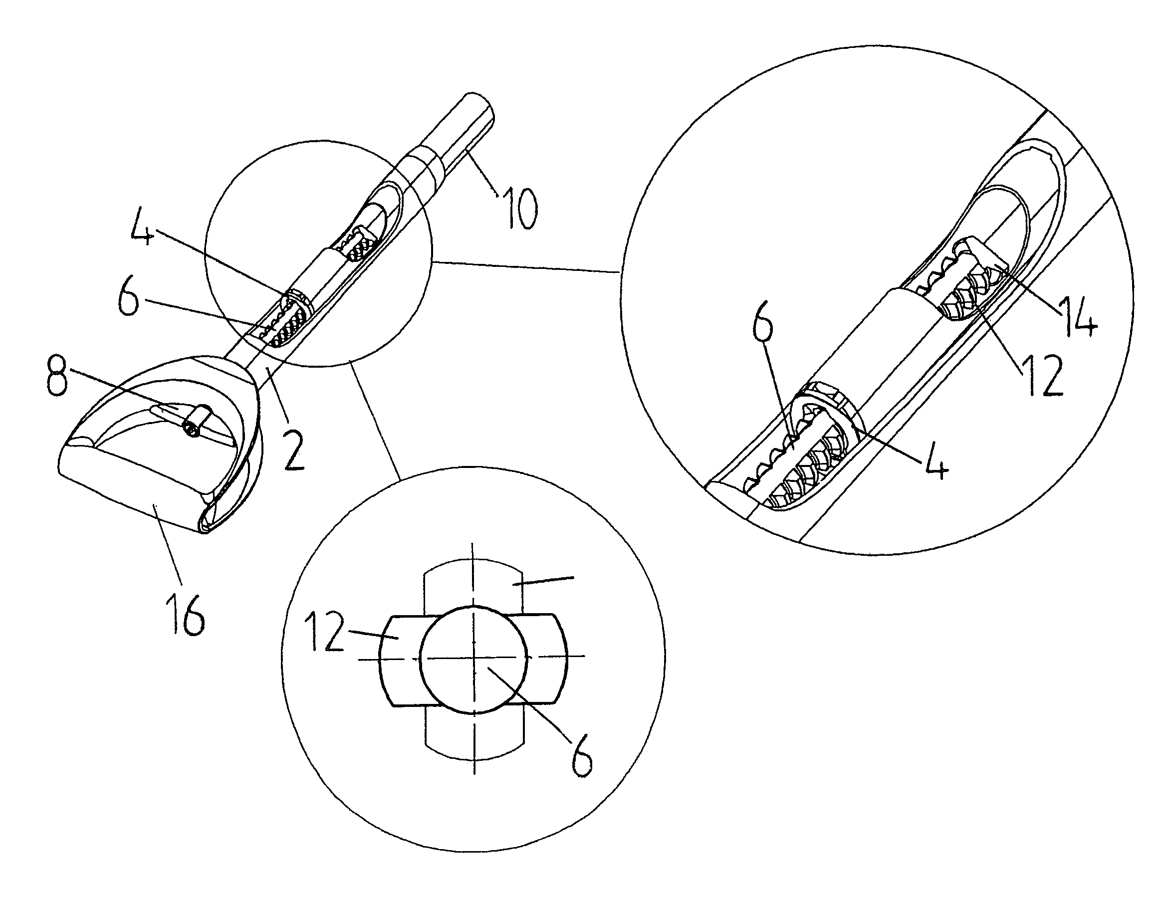
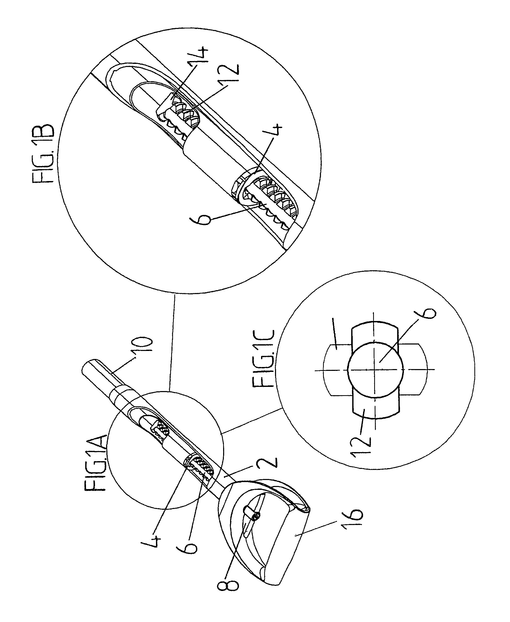
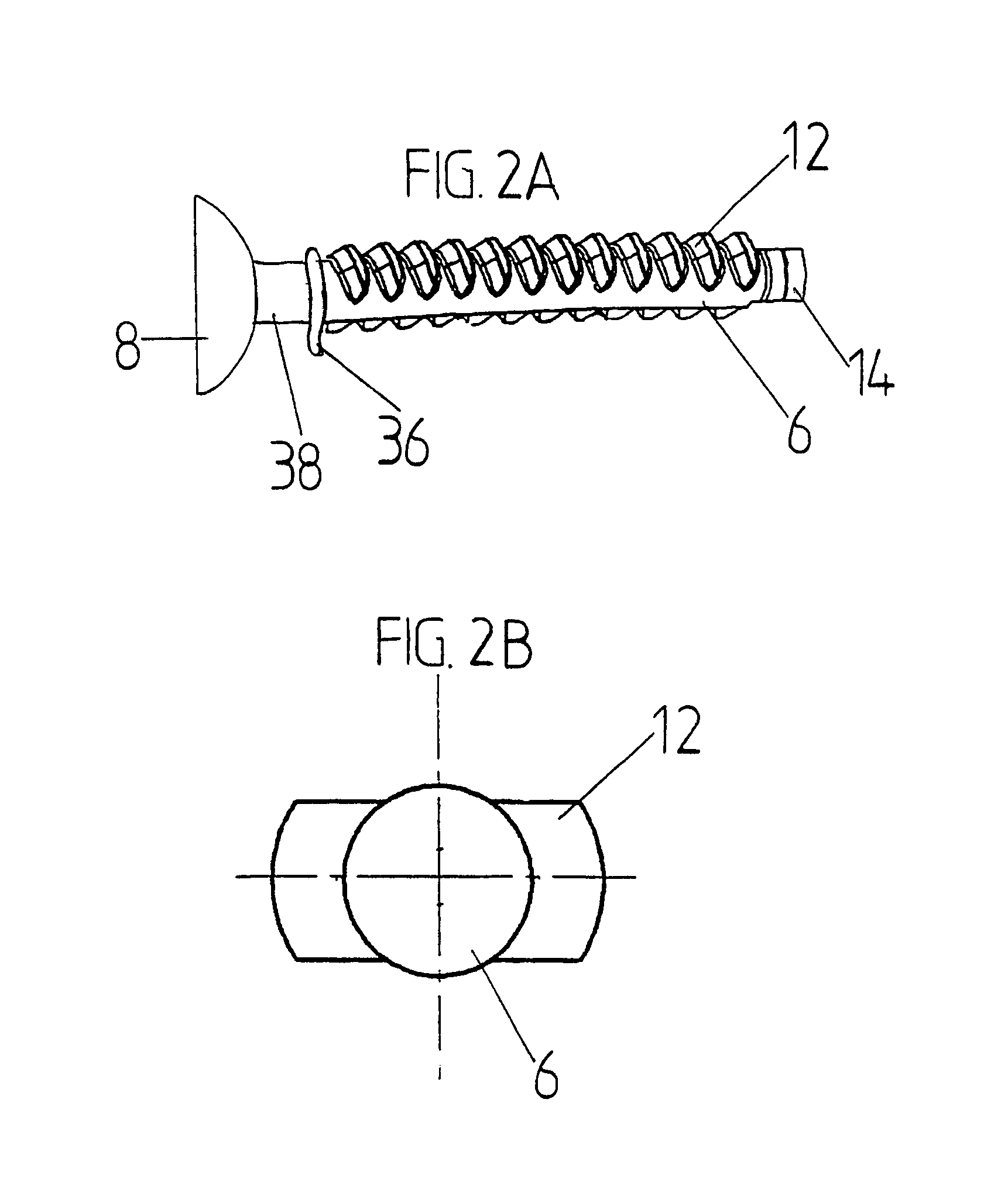
[0020]FIG. 1a illustrates a tool shaft with an adjustable length according to an embodiment of the present invention. The shaft comprises a first shaft section and a second shaft section, which are attached to each other by adjusting means and which move telescopically with respect to each other when the shaft length is adjusted. The adjusting means for adjusting the shaft length comprise a sleeve 4 provided in the second shaft section 10 and an at least partly toothed spindle 6 provided in the first shaft section 2, the first end of the spindle being taken through the sleeve 4. The sleeve 4 and the spindle 6 attach the first 2 and the second 10 shaft section adjustably to each other so that the sleeve 4 and the spindle 6 can be turned with respect to each other into a position preventing the adjustment of the shaft length and into a position allowing the adjustment of the shaft length where the spindle 6 can move in the sleeve in the longitudinal direction. The tool used in this em...


PUM


Abstract

The invention relates to a shaft of a tool or the like with an adjustable length, the shaft comprising a first shaft section (2) and a second shaft section (10) which are attached to each other by adjusting means and move telescopically with respect to each other when the shaft length is adjusted. In that case, the adjusting means for adjusting the shaft length comprise a sleeve (4) provided in the second shaft section (10) and an at least partly toothed spindle (6) provided in the first shaft section (2), the first end of the spindle being taken through the sleeve (4). The sleeve (4) and the spindle (6) attach the first (2) and the second (10) shaft section adjustably to each other so that the sleeve (4) and the spindle (6) can be turned with respect to each other into a position preventing the adjustment of the shaft length and into a position allowing the adjustment of the shaft length where the spindle (6) can move in the sleeve (4) in the longitudinal direction.

Description

BACKGROUND OF THE INVENTION[0001]The invention relates to a shaft of a tool or the like according to the preamble of claim 1.[0002]Tools provided with shafts are used in various spheres of life from work to hobbies. What is relevant to the function and use of equipment provided with long shafts is the length of their shafts. Different applications and users require different shaft lengths, and thus it is often advantageous to provide a tool with an adjustable shaft, which allows each user to adjust the shaft length to suit him / her and the application. The use of adjustable shafts in tools provided with long shafts is a prior art solution. Adjustable shafts are used, for example, in shovels, mops and crutches. Furthermore, sticks and poles with long shafts are used in various sports, such as floorball sticks, ski poles and Nordic walking poles which have an adjustable length. Adjustability of the shaft length allows the length of equipment to be adjusted according to each user and ap...

Claims


Application Information

Patent Timeline
Patent Type & Authority Patents(United States)
IPC IPC(8): B25G1/04F16B7/10
CPCB25G1/04F16B7/105Y10T403/57Y10T16/498Y10T16/4554Y10T16/44Y10T16/473
Inventor LINDEN, OLAVIHUTTUNEN, AARO
Owner FISKARS CONSUMER
Why Eureka
Try Eureka