Hood retaining structure for heat-dissipating device

Inactive Publication Date: 2006-08-15
CHAUN CHOUNG TECH
View PDF9 Cites 24 Cited by
  • Summary
  • Abstract
  • Description
  • Claims
  • Application Information

AI Technical Summary

Benefits of technology

[0011]Moreover, a plurality of four guiding rods are integrally formed on four corners of the hood and corresponding to the retaining hole defined on the fan. To assembl

Problems solved by technology

The CPU will generate considerable heat as the computation speed thereof is rapidly in

Method used


Image

  • Hood retaining structure for heat-dissipating device
  • Hood retaining structure for heat-dissipating device
  • Hood retaining structure for heat-dissipating device

Examples


Example

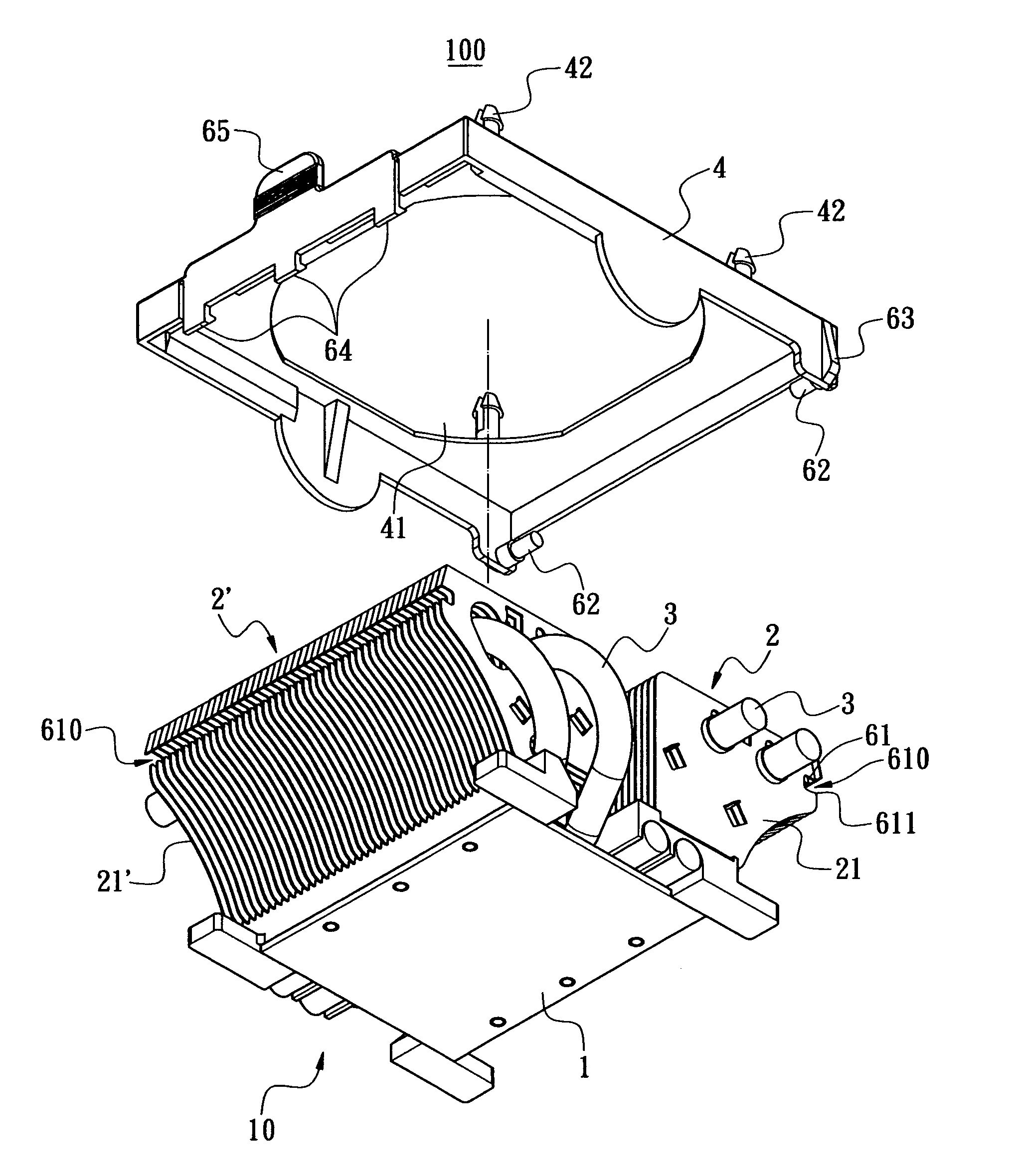
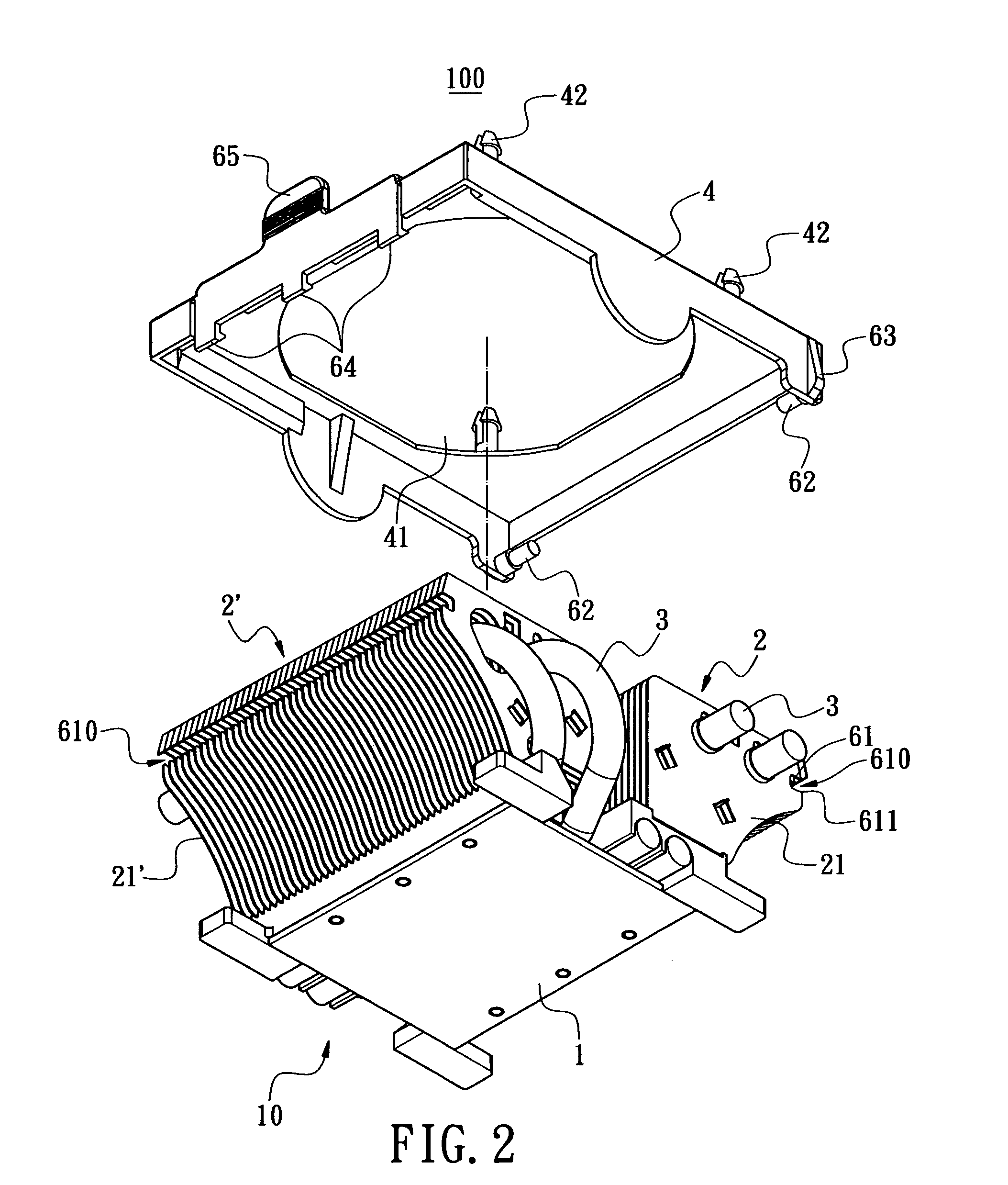
[0019]The present invention provides a hood retaining structure for heat-dissipating device. As shown in FIG. 2, the heat-dissipating device 10 comprises a heat sink 10 having a heat-dissipating block 1 with at least one heat-dissipating fin set 2. In the shown preferred embodiment, there are two heat-dissipating fin sets 2, 2′ arranged in juxtaposition. Each of the heat-dissipating fin sets 2, 2′ comprises a plurality of heat-dissipating fins 21, 21′ erected vertically. Moreover, heat pipes 3 pass through the heat-dissipating fin sets 2, 2′ and the heat-dissipating block 1 and each heat pipe 3 has wick structure and working fluid therein. A hood 4 is arranged atop the heat-dissipating fin sets 2, 2′ and the hood 4 functions to retain a fan 5. The hood 4 has a through hole 41 defined at center thereof and the airflow from the fan 5 will flow through the through hole 41 to cool the heat-dissipating fins 21, 21′.

[0020]In the present invention, the hood 4 is retained to the heat-dissip...


PUM


Abstract

A hood retaining structure for a heat-dissipating device. The heat-dissipating device includes a heat sink with at least one heat-dissipating fin set, and each heat-dissipating fin set includes a plurality of heat-dissipating fins erected vertically. The hood retaining structure is arranged on the heat-dissipating fins to retain a hood thereon and a fan is able to retain to the hood. The hood retaining structure includes a dent defined on an outer side of each heat-dissipating fin such that a retaining groove is defined after the heat-dissipating fin are assembled and at least one retaining rod and at least one retaining hook provided on lateral sides of the hood, the retaining rod and the retaining hook being configured to lock into the retaining groove. The retaining hook includes a push tab.

Description

BACKGROUND OF THE INVENTION[0001]1. Field of the Invention[0002]The present invention relates to a hood retaining structure for heat-dissipating device, and more particularly to a hood retaining structure for heat-dissipating device such that a hood can be easily assembled and disassembled to the heat-dissipating device.[0003]2. Description of Related Art[0004]The computer system generally comprises central processing unit (CPU) on motherboard there for computation and processing. The CPU will generate considerable heat as the computation speed thereof is rapidly increased. Therefore, heat-dissipating device is provided for the CPU and conveys the heat generated by CPU to the ambient outside the computer mainframe, whereby the performance of the CPU is not degraded by high temperature.[0005]FIG. 1 is a sectional view of a prior art heat-dissipating device 10a, which comprises a heat-dissipating block 1a made of material with fast heat dissipation and low heat conductance such as alu...

Claims


Application Information

Patent Timeline
IPC IPC(8): F28F7/00F24H3/06
CPCH01L23/427H01L23/467H01L2924/0002H01L2924/00
Inventor WU, WEN-YUANCHOU, HUNG-MING
Owner CHAUN CHOUNG TECH
Why Eureka
Try Eureka