Actuator adopting the principle of electrostatic induction

a technology of electrostatic induction and actuator, which is applied in the direction of electrostatic generator/motor, dynamo-electric machines, electrostatic motors, etc., can solve the problems of difficult operation at a low speed, short life, and enormous heat generation

Inactive Publication Date: 2006-08-15
OLYMPUS CORP
View PDF15 Cites 7 Cited by
  • Summary
  • Abstract
  • Description
  • Claims
  • Application Information

AI Technical Summary

Benefits of technology

[0011]According to a second aspect of the present invention, there is provided an electrostatic actuator comprising: a stator having two or more inductive electrodes arranged one of substantially parallel and concentric and a plurality of driving electrodes arranged with a predetermined cycle; a movable element having at least two combined electrode structures; and a displacement means for displacing the movable element by generating electric charges in the electrodes of the movable element via the inductive electrodes of the stator, and generating electrostatic force between the electric charges and the driving electrodes of the stator.

Problems solved by technology

Further, the loss of the current flowing in a winding causes enormous heat generation.
They are driven by the frictional force of a piezoelectric transducer, but their life is too short due to deterioration caused by friction.
However, the increased frequency makes it difficult to operate at a low speed.

Method used


Image

  • Actuator adopting the principle of electrostatic induction
  • Actuator adopting the principle of electrostatic induction
  • Actuator adopting the principle of electrostatic induction

Examples


embodiment 1

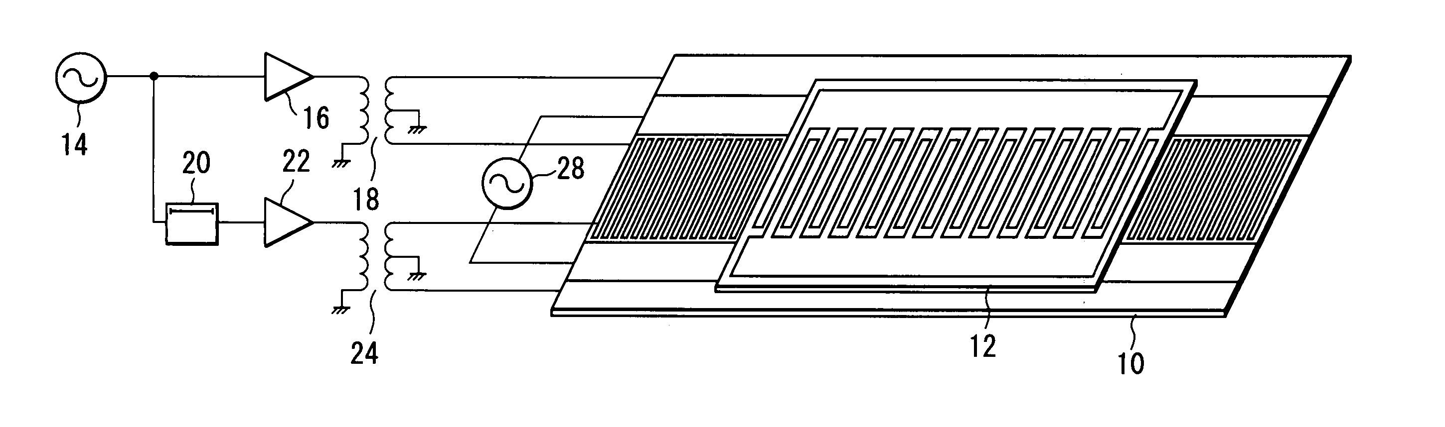
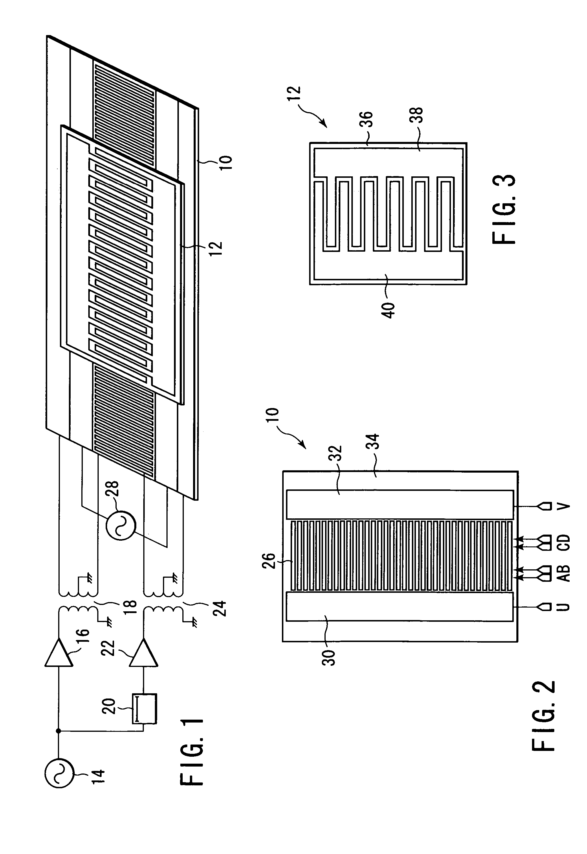
[0046]As shown in FIG. 1, the electrostatic actuator according to a first embodiment of the present invention has a stator 10 and a movable element 12. The stator 10 is supplied with a high-voltage generated by flowing the output signal of an AC generator 14 to an amplifier 16 and a high-voltage transformer 18. At the same time, the stator 10 is also supplied with a high-voltage generated by flowing the output signal of the AC generator 14 delayed by a phase shifter 20 to a high-voltage amplifier 22 and a high-voltage transformer 24. In this case, the outputs of the high-voltage transformers 18 and 24 are applied to driving electrodes 26 of the stator 10 through connection terminals A, B, C and D, as shown in FIG. 2. The output of an AC driving source 28 is applied to inductive electrodes 30 and 32 of the stator 10 through connection terminals U and V. The inductive electrodes 30, 32 and driving electrodes 26 of the stator 10 are built in a film-like insulator 34. A movable element ...

embodiment 2

[0088]The electrostatic actuator according to a second embodiment of the present invention has a disk-like stator 62 and a rotor 64 placed on the stator, a shown in FIG. 17. A driving circuit is the same as that shown in FIG. 1. Inductive electrodes of the disk-like stator 62 are arranged circumferentially inside and outside of the circle. Driving electrodes are arranged radially from the center. In the rotor 64, two comb-like electrodes are interdigitated so that the comb teeth are radially arranged and the comb-like electrode bases are arranged inside and outside of the circumference. When it is driven, it is rotated naturally around a center 66 while keeping the rotation balance. Therefore, a rotation mechanism such as a bearing to prevent rotation shifts is not necessarily provided at the center of the rotor.

[0089]In the above-mentioned rotary actuator, the comb-like electrodes of the rotor are supplied with true electric charges by electrostatic induction. Therefore, a rotation...

embodiment 3

[0090]In the electrostatic actuator according to a third embodiment of the present invention, a cylindrical movable element 68 is arranged outside of a cylindrical stator 70, as shown in FIG. 18, and the cylindrical movable element 68 moves parallel on a cylinder shaft. A driving circuit is the same as the configuration shown in FIG. 1 and FIG. 17. Comb-like electrodes 72 and 74 are arranged in the cylindrical movable element 68. In the cylindrical stator 70, inductive electrodes 76 and 78 are arranged opposite to the comb-like electrodes 72 and 74, so that electrostatic induction is effectively executed in the electrode bases of the comb-like electrodes 72 and 74.

[0091]The cylindrical movable element 68 is provided outside of the cylindrical stator 70, but it can be provided inside of the cylindrical stator 70, though not illustrated.

[0092]The above-mentioned cylindrical movable actuator is similar in operation to the function of cylinder / piston. The electrostatic actuator accordin...


PUM


Abstract

An electrostatic actuator comprises a movable element provided with electrodes, and a stator provided with inductive electrodes for generating electrostatic induction in the electrodes of the movable element. The electrodes of the movable element includes a driven electrode part provided at a position opposite to the driving electrodes of the stator, and an induced electrode part provided at a position opposite to the inductive electrodes of the stator. The movable element is displaced relatively to the stator by generating electrostatic force between the driving electrodes of the stator and the driven electrode part in the movable element in which the electrostatic induction is generated, by applying a voltage to the driving electrodes of the stator, while generating electrostatic induction in the electrodes of the movable element through the induced electrode part by applying a voltage to the inductive electrodes of the stator.

Description

CROSS-REFERENCE TO RELATED APPLICATIONS[0001]This application is based upon and claims the benefit of priority from prior Japanese Patent Application No. 2003-090061, filed Mar. 28, 2003, the entire contents of which are incorporated herein by reference.BACKGROUND OF THE INVENTION[0002]1. Field of the Invention[0003]The present invention relates to an electrostatic actuator which is operated by the action of static electricity, and a method of displacement.[0004]2. Description of the Related Art[0005]A conventional actuator and motor are operated mostly by the action of electromagnetic force, and the weights of the permanent magnet and iron core are heavy. Further, the loss of the current flowing in a winding causes enormous heat generation.[0006]On the other hand, an ultrasonic actuator and an ultrasonic motor operated by forces other than electromagnetic force are known. They are driven by the frictional force of a piezoelectric transducer, but their life is too short due to deter...

Claims


Application Information

Patent Timeline
Patent Type & Authority Patents(United States)
IPC IPC(8): H02N1/00
CPCH02N1/004H02K2201/18
Inventor GONDOH, MASAHIKO
Owner OLYMPUS CORP
Why Eureka
Try Eureka