Snap-hook tether

a technology of tether and snap, which is applied in the field of snaphooks, can solve the problems of user difficulty in depressing/opening the snap, the user's hand-held snap is swivel, and the operation of two hands is difficult, etc., and achieves the effect of convenient operation, flexibility and convenien

Inactive Publication Date: 2006-08-22
FERGUSON THOMAS
View PDF10 Cites 8 Cited by
  • Summary
  • Abstract
  • Description
  • Claims
  • Application Information

AI Technical Summary

Benefits of technology

[0006]The present invention addresses the above needs. In one embodiment, the present invention provides, a snap-hook that allows “one handed” operation. The snap-hook comprises a hook, forming a portion of an eye loop, and a lever that is movable relative to the hook, the lever forming a remaining portion of said eye loop with respect to the hook. A thumb tab is connected to the lever, and is positioned in a slot defined in the hook, whereby the thumb tab is slidable in the slot relative to the hook, forming a release mechanism, such that the sliding movement of the thumb tab in the slot causes the lever to move relative to the hook to open said eye loop. The snap-hook has essentially broad, opposing, front and back sides, and relatively narrower edges, such that the back side of the snap-hook can be placed into the palm of a user's hand to hold the snap, wherein the thumb tab is located on the front side of the snap-hook to allow simpler holding of the snap-hook and operation of the release mechanism with one hand while essentially eliminating swiveling of the snap-hook in the hand.
[0008]Yet in another embodiment, the present invention provides a snap hook comprising a hook section having an open segment, thereby forming a portion of an eye loop, and a lever that is pivotally movable relative to the open segment of the hook section to block and unblock the open segment, the lever forming a remaining portion of said eye loop with respect to the hook section. A biasing means, such as spring, is positioned between the hook and the lever for biasing the lever against pivoting relative to the hook. A tab is connected to the lever, wherein the tab includes an extension disposed in a slot defined in the hook section, such that the tab extension is slidable in the slot relative to the hook section. The tab and the lever form a release mechanism, such that applying force to the tab that overcomes said biasing, effects the tab extension to slide in the slot, thereby causing the lever to pivot relative to the hook section to open said eye loop.
[0009]Therefore, an improved snap-hook according to the present invention provides one-hand, easy, operation and flexibility.

Problems solved by technology

However, it can be difficult to depress / open that snap as the pressure to push the thumb tab down (to open) will cause the snap to swivel in the hand.
The “two handed” operation presents problems to users such as in the equestrian industry.
However, disconnecting / opening this snap-hook from an object with one hand requires great dexterity, and can force the finger(s), used to push / fold back the tab, between the tab and the body of the snap-hook; a potentially hazardous operation.

Method used


Image

  • Snap-hook tether
  • Snap-hook tether
  • Snap-hook tether

Examples


Embodiment Construction

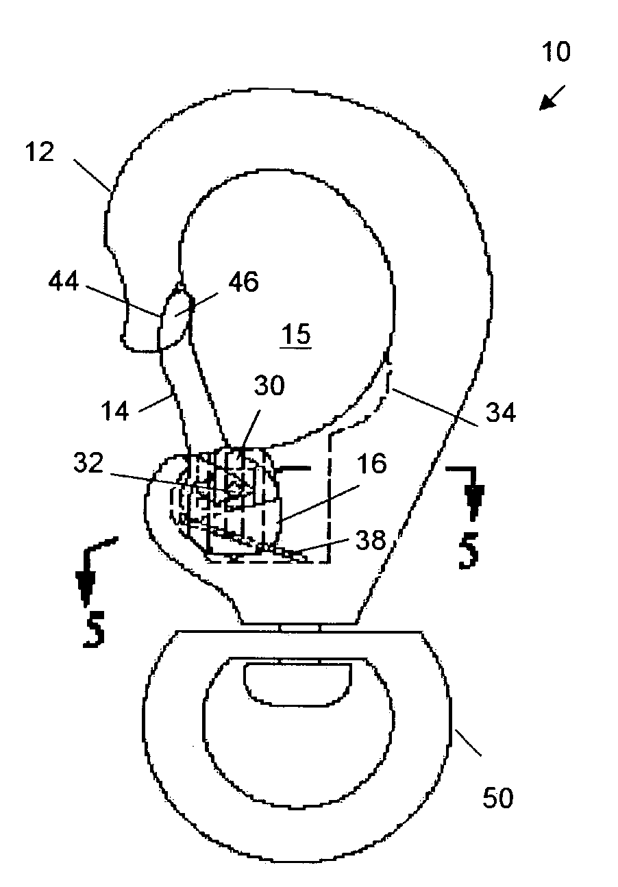
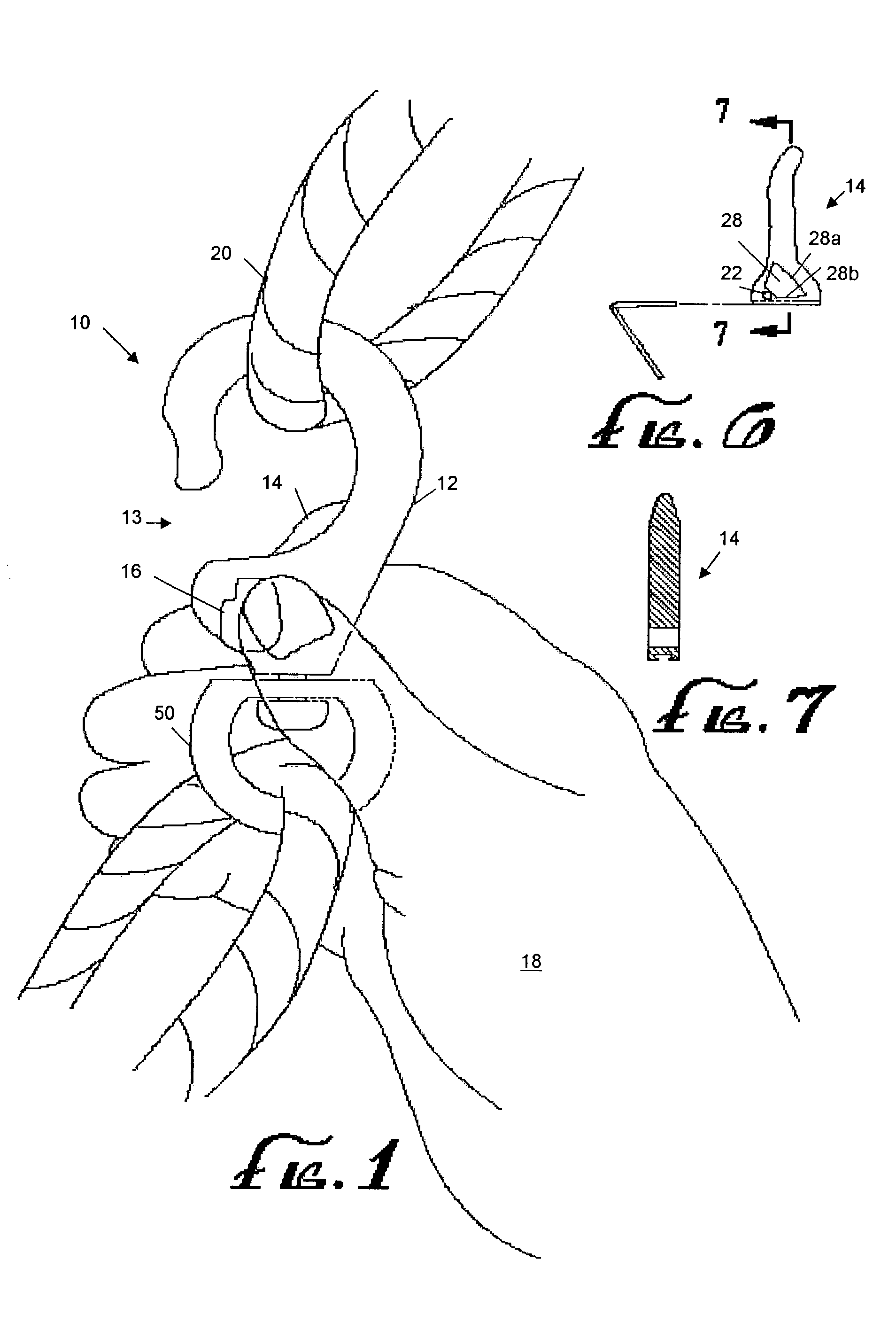
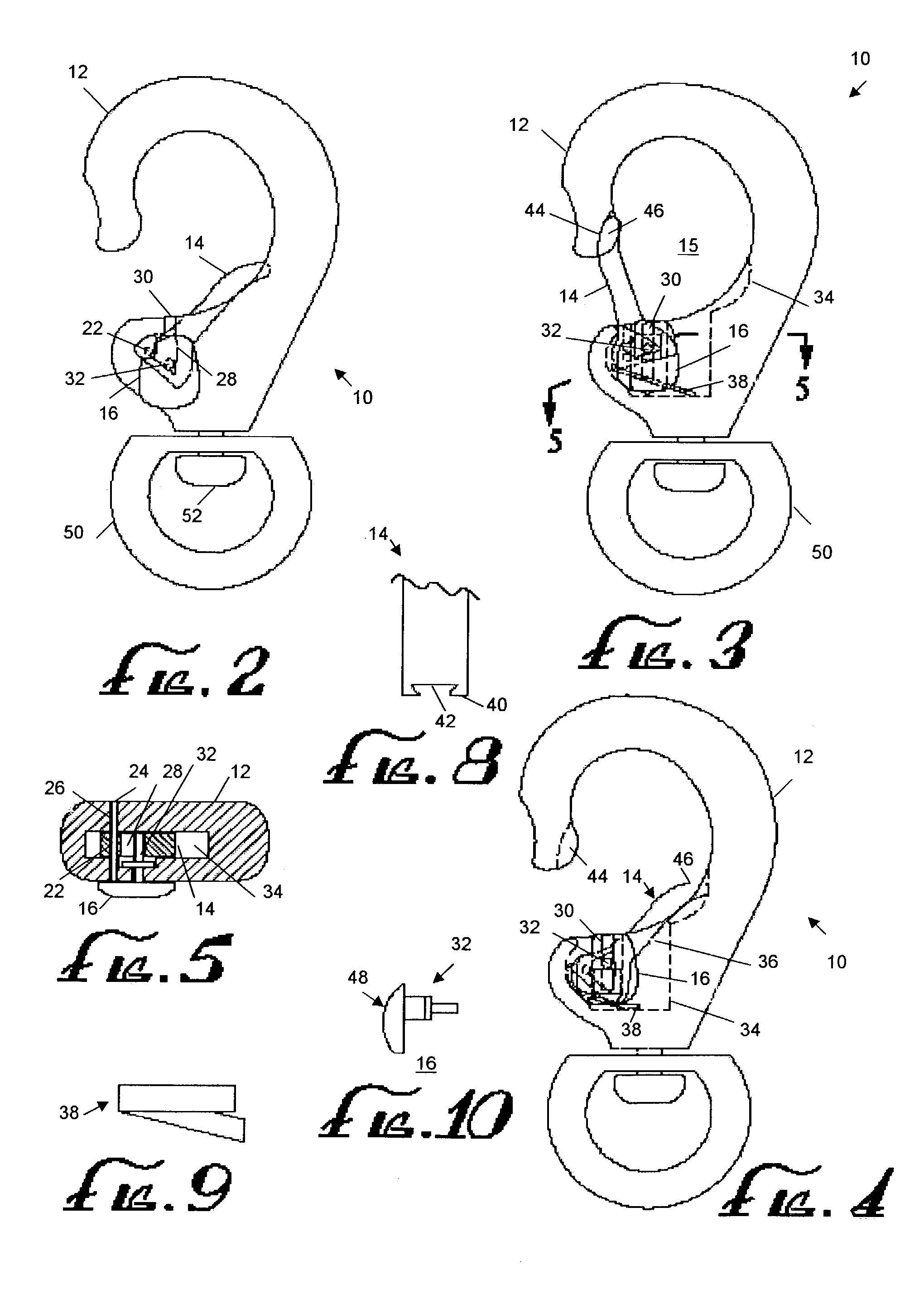
[0021]Referring to FIG. 1, in one embodiment, the present invention provides, a snap-hook 10 that allows “one handed” operation. The snap-hook 10 comprises a hook 12 and a lever 14 that opens / closes the hook. The snap-hook 10 combines an “easy on” feature, along with a thumb actuated tab 16 for moving the lever 14. As shown in FIG. 1, the location of the thumb tab 16 is on the side of the snap-hook 10, facing the user as the snap-hook 10 lays flat in the palm of a user's hand 18.

[0022]As such, the snap-hook 10 provides quick access to the thumb tab 16, and the location of the thumb tab 16 makes it much easier to depress / push down the tab 16 to move the lever 14. This allows for not only a quick and easy release / opening of the snap-hook 10, but also essentially eliminates any swiveling effect associate with conventional snap hooks. This is because the pressure to depress the thumb tab 16 is evenly distributed against the width of the snap-hook 10 as it is properly supported in the pa...


PUM


Abstract

A snap-hook that has a hook, forming a portion of an eye loop, and a lever that is pivotally movable relative to the hook. The lever forms a remaining portion of said eye loop with respect to the hook. A thumb tab is connected to the lever, and is positioned in a slot defined in the hook. The thumb tab is slidable in the slot relative to the hook, forming a release mechanism, such that the sliding movement of the thumb tab in the slot causes the lever to pivot relative to the hook to open said eye loop. The snap-hook has essentially broad, opposing, front and back sides, and relatively narrower edges, such that the back side of the snap-hook can be placed into the palm of a user's hand to hold the snap. The thumb tab is located on the front side of the snap-hook to allow simpler holding of the snap-hook and operation of the release mechanism with one hand while essentially eliminating swiveling of the snap-hook in the hand.

Description

FIELD OF THE INVENTION[0001]The present invention related to the field of snap-hooks, and in particular, to the field of snap-hooks for outdoor and equestrian applications.BACKGROUND OF THE INVENTION[0002]Snap hooks are used for a variety of purposes. Typically a snap-hook includes a hook and a lever that opens / closes the hook. Bolt snap-hooks provide a thumb operated spring-loaded plunger, with an up and down motion. To open the bolt snap-hook, pressure is applied to a thumb tab to push down the plunger. However, it can be difficult to depress / open that snap as the pressure to push the thumb tab down (to open) will cause the snap to swivel in the hand. This is due to the tab's location on the narrow width / edge of the snap. Also, the thumb tab must be depressed to attach the snap to an object.[0003]Bull snap-hooks employ a swivel tab that pulls forward to open the snap-hook. However, this requires the use of two hands; one to hold the snap-hook and another to pull the tab outward. T...

Claims


Application Information

Patent Timeline
Patent Type & Authority Patents(United States)
IPC IPC(8): F16B45/02
CPCF16B45/02Y10T24/45414Y10T24/45361Y10T24/45346F16B45/023F16B45/026
Inventor FERGUSON, THOMAS BURTONMCDONALD, MICHAEL HANLEY
Owner FERGUSON THOMAS
Why Eureka
Try Eureka