Perforating gun with a holding system for hollow charges for a perforating gun system

a perforating gun and holding system technology, applied in the field of perforating guns of perforating gun systems, can solve the problems of inability to absorb pressure load, high cost, and high system instability, and achieve the effect of increasing the number of hollow charges or the number of charges per length of the perforating gun

Active Publication Date: 2019-08-06
DYNAENERGETICS
View PDF20 Cites 0 Cited by
  • Summary
  • Abstract
  • Description
  • Claims
  • Application Information

AI Technical Summary

Benefits of technology

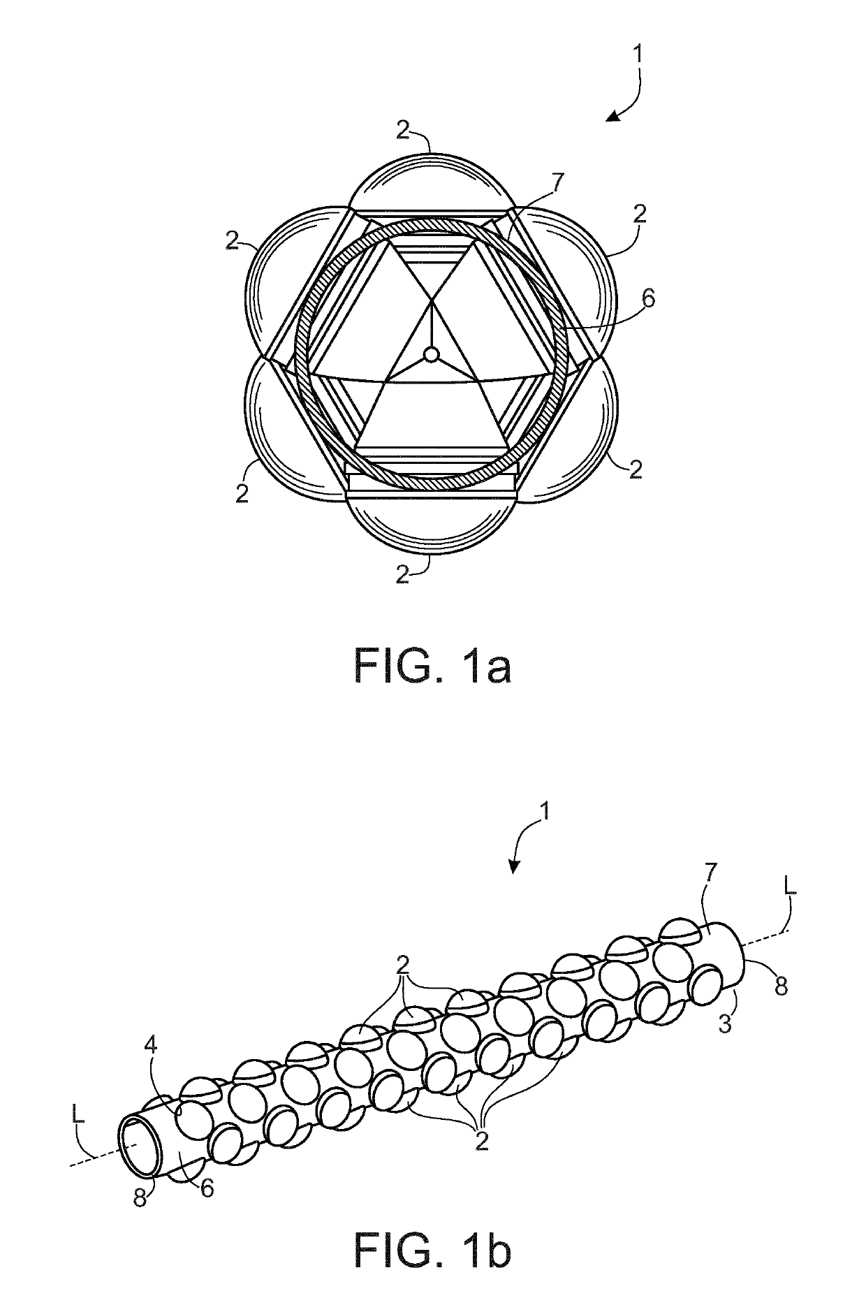
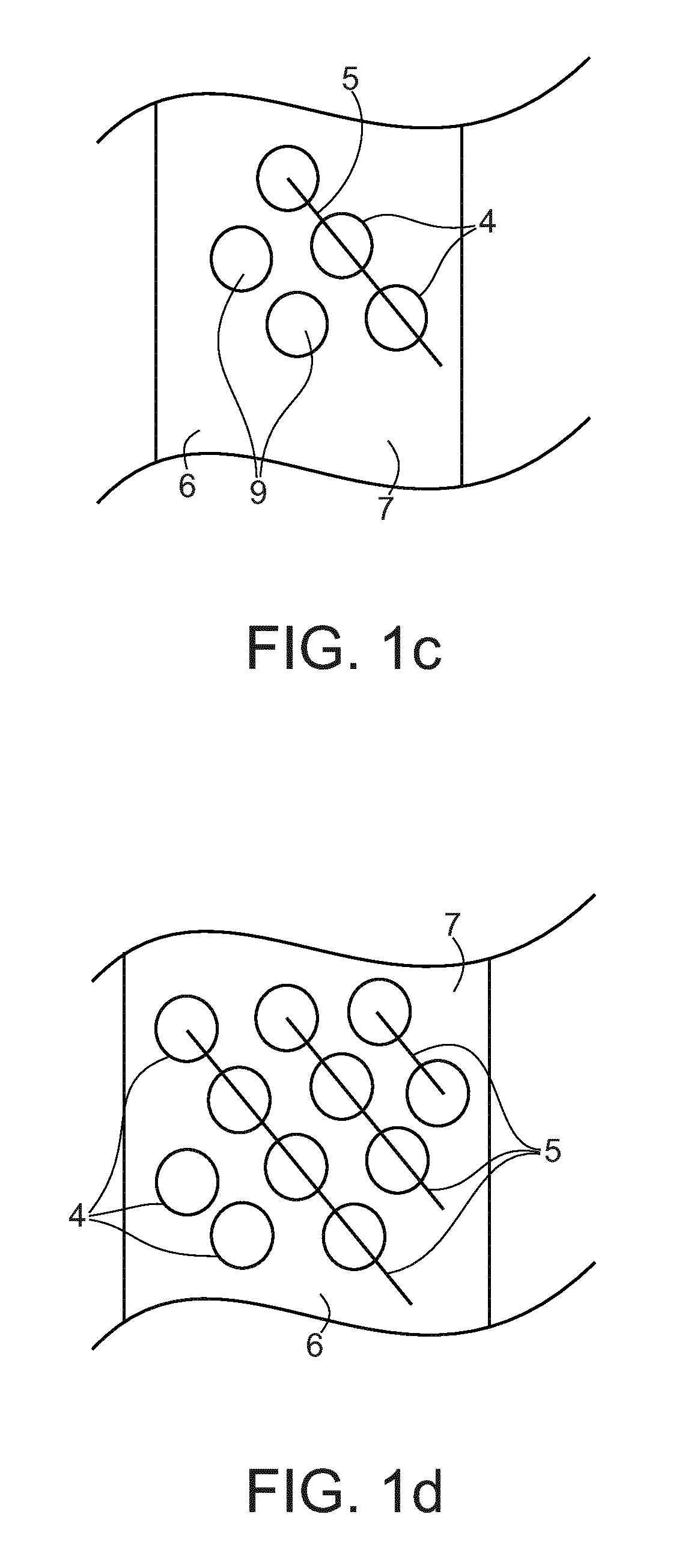
[0007]Another object is achieved by each individual hollow charge being encapsulated hydraulically sealed, the holding device including at least one pipe or tube, on the circumferential surface of which the holes are arranged either on at least one helix or on multiple, parallel extending helices. In perforating guns according to the state of the art, the holding devices, upon which the hollow charges are secured, are coaxially enclosed by a pipe, whereby the hollow charges are sealed-off from external influences. Since according to an embodiment, each individual hollow charge is encapsulated and hydraulically sealed, a simple holding device without expensive separators, seals or the like will do as perforating gun. In this way, the hollow charges are positioned close to one another and require less space, which allows a higher number of charges per foot of the length of the gun / holding device than has previously been commercially available, in for instance, a normal capsulated gun system. The perforating gun according to an embodiment is therefore much lighter than those in the state of the art.
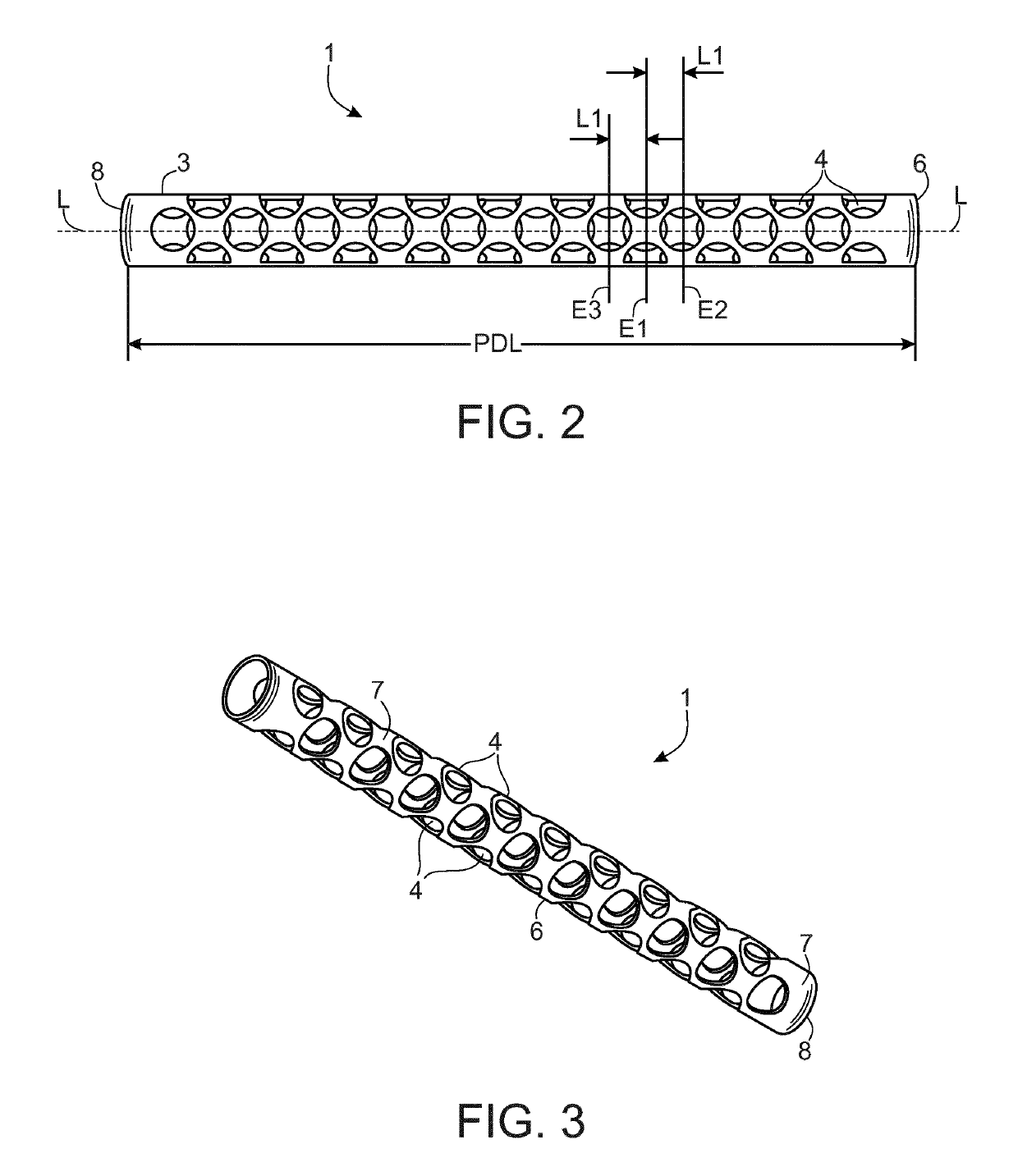
[0013]In an embodiment, the centers of all holes (for the hollow charges) are arranged on planes (E1, E2, E3) which are perpendicular to the longitudinal axis L of the at least one pipe and extend parallel to each other, and both of the two adjacent planes are arranged at the same distance L1 from one another, and the same number of holes or their centers is arranged on all planes, and the centers of the holes on one plane E1 are offset from the centers of the holes on the adjacent planes E2 and E3 in order to increase the number of hollow charges or the charge density.
[0017]The perforating gun according to an embodiment relates is characterized by a high stability and imperviousness to hydraulic pressure. It is also configured to withstand a compressional load along the longitudinal axis, which exceeds the weight of the system many times over. When suspended in the borehole, the perforating gun is able to carry its own weight while suspended. These properties are achieved by the use of encapsulated hydraulically sealed hollow charges, the material of which allows for being broken down into the smallest of pieces. The holding device for the hollow charges is a pipe of steel, plastic or the like with a pattern of holes. The holes are used for inserting the hollow charges, which are secured therein. The arrangement of the charges in a single, double, triple or multiple helix enables breaking the pipe up into the smallest of pieces or fragments as a result of the detonation. The required stability of the pipe to withstand compression and tension is achieved by the geometry of the pattern of holes (helix helices) and the thickness as well as the material of the pipe. Also, the diameter of the pipe exerts an influence on the stability.
[0018]The perforating gun may consist of one or more such pipes with hollow charges. The pipes are then, where appropriate, connected by connecting mechanisms, which also remain in the borehole after detonation. The use of ballistic transmission mechanisms between the segments allows for a joint ignition of all the explosive charges contained in the whole system by an initiation system. Transmission and initiation systems are also able to withstand the aforementioned hydraulic pressure.
[0020]If the pipes are divided into individual planes E, all of which extend parallel to one another and perpendicular to the longitudinal axis L of the pipes, then two adjacent planes will be arranged at the same distance L1 from one another, respectively. On these planes, the holes or the centers of the holes are arranged on the pipes. On all planes, the same numbers of holes are arranged on the pipes. Considering a first plane E1, the centers of the holes on adjacent planes E2 and E3 are each offset from the holes on the first plane in order to increase the number of hollow charges or the charge density.

Problems solved by technology

These also remain in the borehole; such systems, however, are much more unstable.
They therefore cannot absorb any pressure load.
This requires time and involves costs.

Method used


Image

  • Perforating gun with a holding system for hollow charges for a perforating gun system
  • Perforating gun with a holding system for hollow charges for a perforating gun system
  • Perforating gun with a holding system for hollow charges for a perforating gun system

Examples


Embodiment Construction

[0032]Hereinafter, embodiments will be exemplified with reference to the Figures.

[0033]FIG. 1b shows a pipe 6 as a holding device 3 of a perforating gun 1 with encapsulated hollow charges 2 inserted in holes 4. By “encapsulated”, what is meant is that the normally “open end” of the hollow charge 3, (the end comprising a liner), is enclosed as if in a capsule by a protective member. By “hydraulically sealed,” what is meant is that it is configured so as to form a sealed assembly capable of blocking fluid up to 400 bar pressure.

[0034]If the perforating gun 1 is to be lowered into a wellbore without benefit of an outer housing or casing, (i.e., the system is an exposed system), there must be some mechanism for maintaining the charge or explosive formed along an inner wall of the hollow charge 2 in a sealed fashion such that no wellbore fluids, water, or the like, are capable of seeping into the hollow charge and thus rendering the charge incapable of discharging. An embodiment provides...


PUM


Abstract

A perforating gun of a perforating gun system is provided including hollow charges positioned within a holding device. The holding device includes holes in which the hollow charges are inserted and secured. In an embodiment, the holes are arranged on at least one helix. In a further embodiment, the perforating gun provides collapsible and fragmentable components that minimize debris remaining in a wellbore upon detonation of the charges.

Description

CROSS-REFERENCE TO RELATED APPLICATIONS[0001]This application claims priority to PCT Application No. PCT / EP2013 / 070912, filed Oct. 8, 2013, which claims priority to German Patent Application No. 102012019652.0, filed Oct. 8, 2012, each of which are incorporated herein by reference in their entirety.FIELD[0002]A perforating gun of a perforating gun system, is provided with hollow charges and with a holding device having holes in which the hollow charges are inserted and secured.BACKGROUND[0003]A perforating gun system denotes a system for hollow charges, holding devices for the hollow charges, connecting pieces of the holding device, as well as ballistic initiation and transmission mechanisms, e.g. the detonating cord for firing the hollow charges. The purpose of the perforating gun system is the perforation of pipes in boreholes using hollow charges. A perforating gun is to be understood as a holding device to which, amongst other things, the hollow charges are secured. The ballisti...

Claims


Application Information

Patent Timeline
Patent Type & Authority Patents(United States)
IPC IPC(8): E21B43/117
CPCE21B43/117
Inventor MCNELIS, LIAMLOHKEN, JORN OLAFBERNARDI, JR., LOUIS ANTHONYBRINSDEN, MARK SHELLEY
Owner DYNAENERGETICS
Why Eureka
Try Eureka