Stair-stepped angled patch panel

a patch panel and angled technology, applied in the direction of optical elements, coupling device connections, instruments, etc., can solve the problems of difficult access to the plugs, the possibility of connector interference on the rear side of the patch panel, and the prior angled patch panel has some drawbacks, so as to achieve better accessability

Active Publication Date: 2006-08-22
PANDUIT
View PDF40 Cites 158 Cited by
  • Summary
  • Abstract
  • Description
  • Claims
  • Application Information

AI Technical Summary

Benefits of technology

[0006]It is also desirable to provide a patch panel with better accessabilit...

Problems solved by technology

However, prior angled patch panels have some drawbacks.
Because the connectors extend rearward of the patch panel a substantial distance and are angled inward toward an imaginary center line due to their orthogonal orientation, there is a po...

Method used


Image

  • Stair-stepped angled patch panel
  • Stair-stepped angled patch panel
  • Stair-stepped angled patch panel

Examples


Embodiment Construction

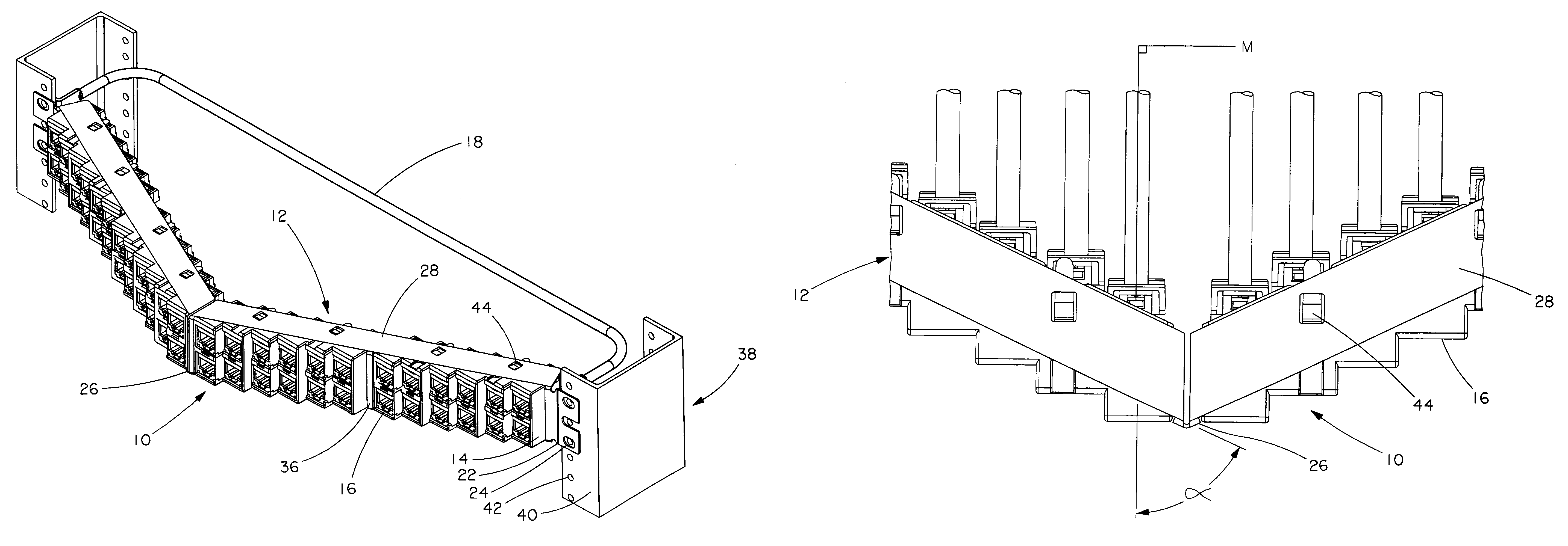
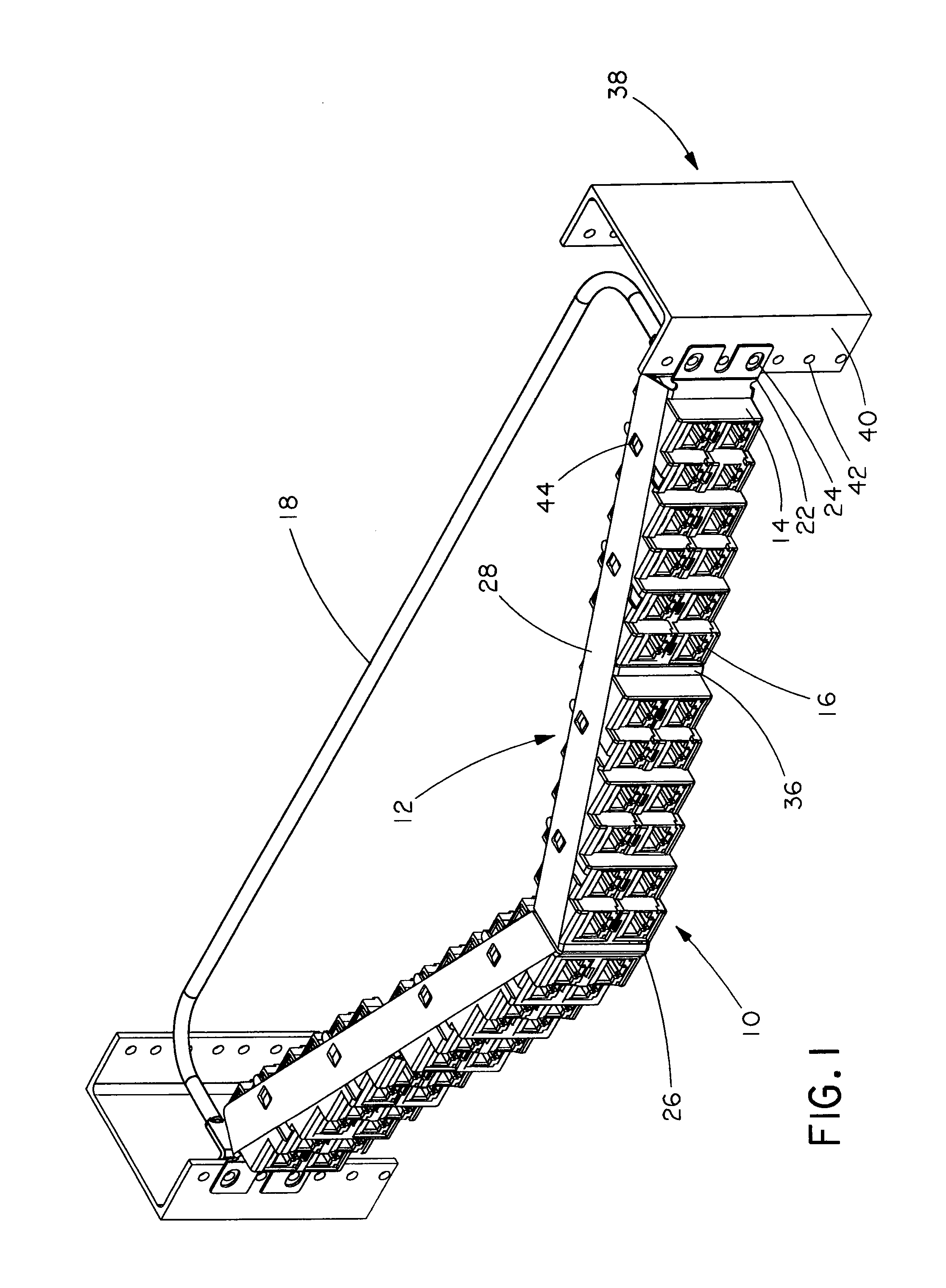
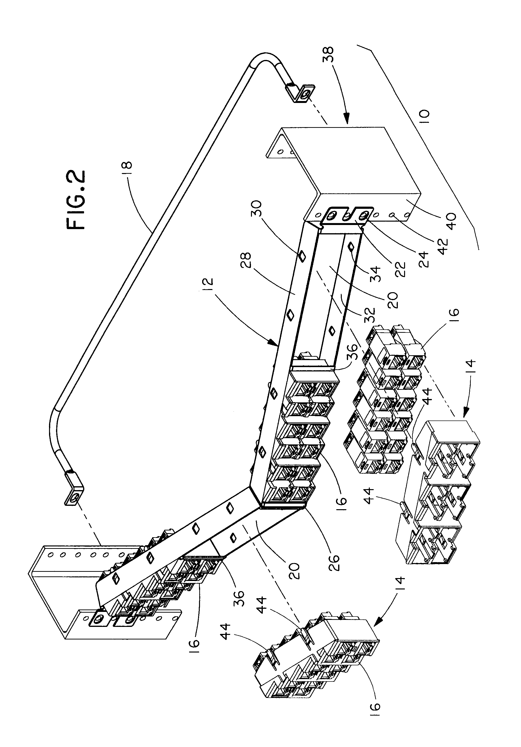
[0015]FIGS. 1–4 are directed to a high density angled patch panel utilizing four, twelve-position faceplates for a total of forty-eight ports in one rack unit. One rack unit is 1.75 inches high under the EIA / TIA standard. However, it is likewise contemplated that the patch panel may include any number of faceplates having any number of positions. For example, the patch panel may include only two, twenty-four position faceplates.

[0016]FIG. 1 shows a fully loaded high density angled patch panel 10. As best seen in FIG. 2, the patch panel 10 includes a frame 12, a plurality of faceplates, such as faceplate 14, and a plurality of connectors, such as connector 16. Moreover, a separate or integral cable support bar 18 may be provided on a rear side of the patch panel 10. Preferably, the frame 12 is metal, and the faceplate 14 is plastic. However, it is likewise contemplated that the frame 12 may be formed of any suitable rigid material, such as many plastics or composites.

[0017]The outwar...


PUM


Abstract

An angled patch panel is mountable to a network rack. The angled patch panel includes a patch panel frame, rack mounting members provided on opposite longitudinal ends of the frame, and a plurality of connectors mountable on the frame. The frame has a first panel section and a second panel section angled relative thereto by an obtuse angle between 90° and 180°. The first and second panel sections each define a front surface, and the plurality of connectors are oriented at an acute angle α relative to the front surface of either the first or second panel sections.

Description

CROSS-REFERENCE TO RELATED APPLICATIONS[0001]This application claims priority to U.S. Provisional Application Nos. 60 / 656,253, filed Feb. 25, 2005, and 60 / 765,316, filed Feb. 3, 2006, the entire contents of which are hereby incorporated by reference.FIELD OF INVENTION[0002]The present invention is directed to an angled patch panel for a network equipment rack and, more particularly, an angled patch panel having a plurality of connectors mounted at an acute angle relative to the faceplate surface. Preferably, the connectors are mounted substantially perpendicular to the plane of the network equipment rack.DESCRIPTION OF RELATED ART[0003]Angled patch panels are known in the art, as shown and described in U.S. Pat. No. 6,866,541. In prior angled patch panels, connectors are oriented orthogonal to the faceplate surface. This angled configuration allows cables exiting the front of the connectors to flow directly to one or more vertical cable managers located adjacent the network rack and...

Claims


Application Information

Patent Timeline
IPC IPC(8): H01R13/66H01R9/22
CPCG02B6/3897G02B6/4452H04Q1/13H04Q1/068H04Q1/062H01R13/518H04Q2201/02
Inventor CAVENEY, JACK E.
Owner PANDUIT
Why Eureka
Try Eureka