Power supply coupling terminal

a technology of power supply coupling and power supply connector, which is applied in the direction of coupling device details, coupling device connection, electric discharge lamp, etc., can solve the problems of power supply connector not being inserted in the mainboard slot, power supply output voltage drop of power supply p often occurring, and power supply received by the computer host could not be adequa

Inactive Publication Date: 2006-08-22
TOPOWER COMP IND CO LTD
View PDF4 Cites 33 Cited by
  • Summary
  • Abstract
  • Description
  • Claims
  • Application Information

AI Technical Summary

Benefits of technology

[0004]The improved power supply coupling terminal according to the invention mainly includes first coupling slots on an upper end and second coupling slots on a lower end that oppose each other and are not connected by conductive wires thereby may be coupled with different types of power supply connectors and mainboard insertion slots to prevent defects and output voltage drop of the power supply and also to reduce molding, material, and fabrication and assembly costs.

Problems solved by technology

But if the power supply connector has twenty slots while the mainboard socket has twenty-four slots, or the power supply connector has twenty-four slots while the mainboard socket has twenty slots, the power supply connector cannot be inserted in the mainboard slots.
Hence defects and output voltage drop of the power supply P often occur.
Power supply received by the computer host could be not adequate.
Molding, material, and fabrication and assembly costs are higher.

Method used


Image

  • Power supply coupling terminal
  • Power supply coupling terminal
  • Power supply coupling terminal

Examples


Embodiment Construction

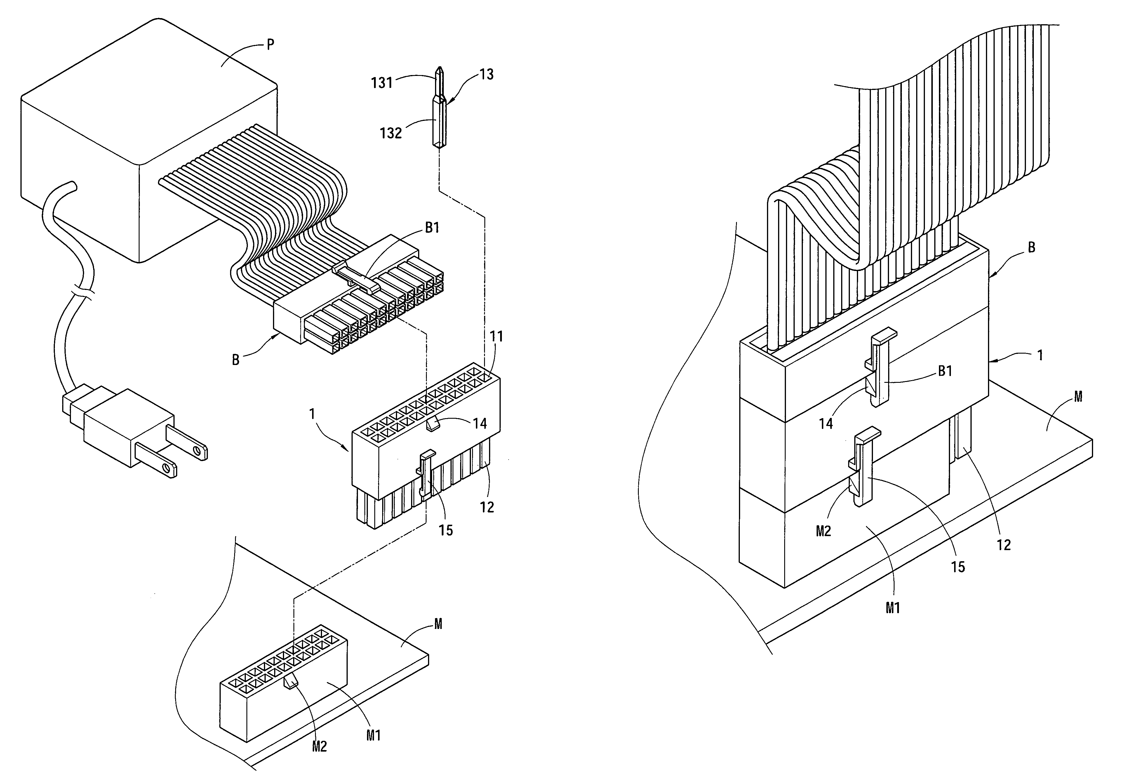
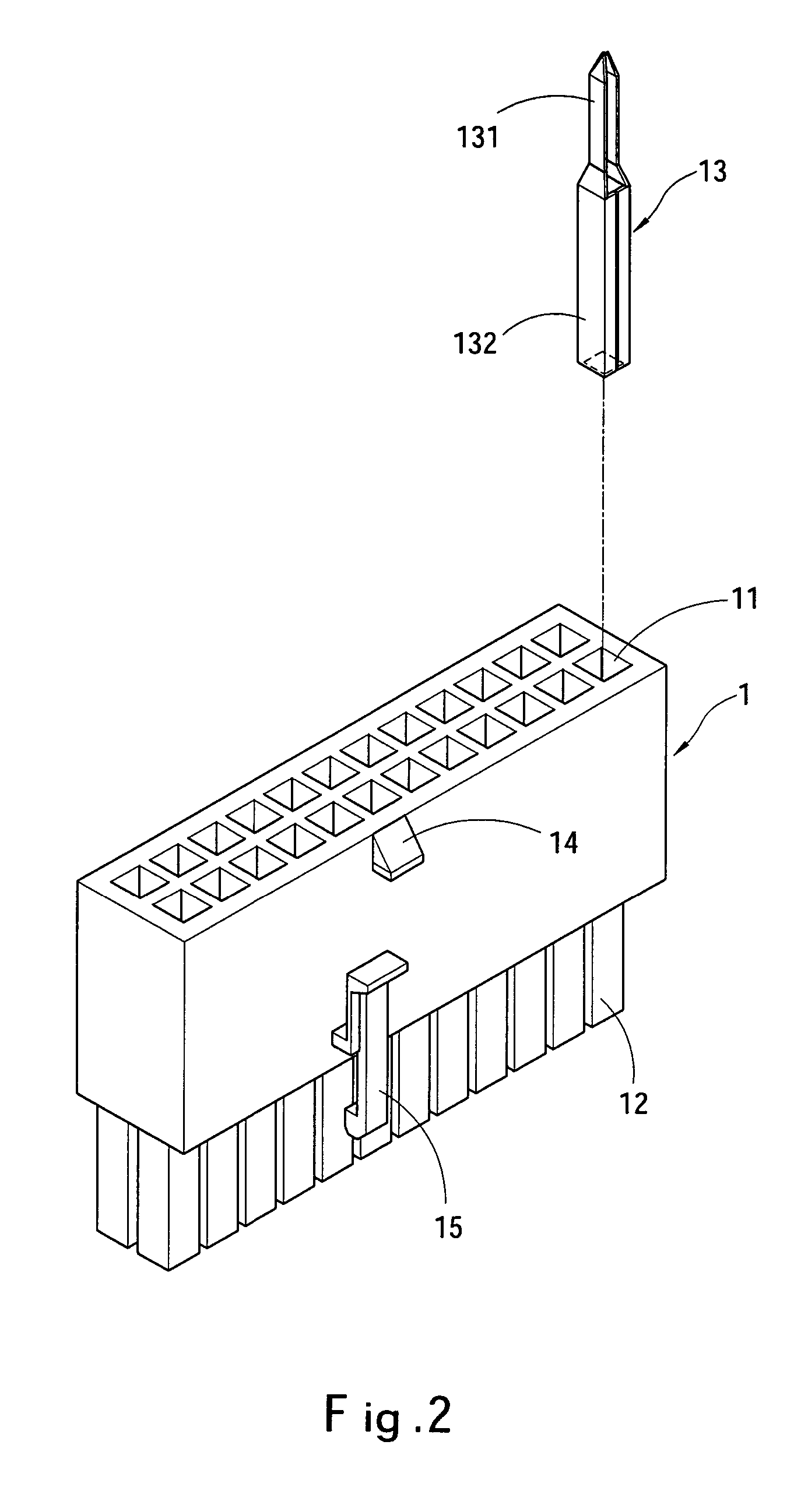
[0013]Please referring to FIGS. 2, 3 and 4, the power supply coupling terminal 1 according to the invention mainly includes twenty-four first coupling slots 11 on an upper end, and twenty-four second coupling slots 12 on a lower end that oppose each other and are not connected by conductive wires. Each of the first coupling slots 11 and the second coupling slots 12 is coupled with a coupling pin 13 which has a male connector 131 on one end and a female socket 132 on other end. Hence a connector B of a power supply P can be coupled and connected electrically with the male connector 131 of the coupling pin 13, and the second coupling slots 12 of the coupling terminal 1 may be coupled with insertion slots M1 of a mainboard M. It is to be noted that the main feature previously discussed targets the power supply connector B with twenty-four slots to output electric signals to the insertion slots M1 of the mainboard M that have twenty slots. Namely four slots of the first coupling slots 1...


PUM


Abstract

An improved power supply terminal to prevent defects and output voltage drop of the power supply and reduce the total cost, and to bridge a power supply connector and insertion slots of a mainboard includes twenty-four first coupling slots on an upper end and twenty or twenty-four second coupling slots on a lower end. The coupling slots are opposing each other and not connected by conductive wires. Thereby it can be coupled with different types of power supply connectors and mainboard insertion slots. Defects and output voltage drop of the power supply can be prevented. Due to no conductive wires and separated design of the coupling slots and the coupling pins is not necessary, molding, material, and fabrication and assembly costs are reduced.

Description

FIELD OF THE INVENTION[0001]The present invention relates to an improved power supply coupling terminal for bridging a power supply connector and insertion slots of a mainboard that has first coupling slots on an upper end and second coupling slots on a lower end that oppose each other and are not connected by any conductive wires to be coupled with different types of power supply connectors and mainboard insertion slots to prevent defects and output voltage drop of the power supply and also reduce molding, material, and fabrication and assembly costs.BACKGROUND OF THE INVENTION[0002]Power supply is an indispensable device for normal operation of a computer. The power supply has an output connector to couple with a power supply socket of the mainboard. The power supply connectors now on the market generally have two types: one has twenty slots, the other has twenty-four slots. The mainboard socket also has two types: one has twenty slots and the other has twenty-four slots to mate t...

Claims


Application Information

Patent Timeline
Patent Type & Authority Patents(United States)
IPC IPC(8): H01R25/00H01R12/24H01R13/66H01R31/06
CPCH01R31/065H01R23/667H01R13/6675H01R12/7088H01R12/79H01R12/00
Inventor CHOU, CHING-LIN
Owner TOPOWER COMP IND CO LTD
Why Eureka
Try Eureka