Multi-leaf collimator

a collimator and multi-leaf technology, applied in the field of multi-leaf collimators, can solve the problems of increased likelihood of recurrence, longer recovery time after treatment, and increased side effects, and achieve the effect of improving resolution and large field siz

Active Publication Date: 2006-08-22
ELEKTA AB
View PDF7 Cites 57 Cited by
  • Summary
  • Abstract
  • Description
  • Claims
  • Application Information

AI Technical Summary

Benefits of technology

[0007]The present invention seeks to provide a multi-leaf collimator which further alleviates the problems of inter-leaf leakage and pixellation and provides improved resolution and large field size.
[0012]The penumbra is the region close to the radiation field edge. The penumbral width is typically defined by the distance between the points where 20% and 80% of the dose at central axis is delivered. A small penumbra means a good beam definition which allows to give maximum dose to a target volume with a rapid dose fall off next to it towards the surrounding normal healthy tissue.

Problems solved by technology

If areas are left untreated then the likelihood of recurrence is increased, whereas if non-treatment regions are irradiated then damage will be caused to healthy tissue resulting in greater side effects and longer recovery times after treatment.
Multi-leaf collimators generally suffer from two difficulties.
However, inter-leaf leakage is a limiting factor in some treatment plans such as Intensity Modulated Radiation Therapy (IMRT) where the treatment time is relatively long.
The pixellation issue is a factor related to the resolution of the leaf bank, and therefore efforts to alleviate this problem tend to involve the use of narrower leaves.
This does, however, make the collimator more complex and present significant engineering challenges.

Method used


Image

  • Multi-leaf collimator
  • Multi-leaf collimator
  • Multi-leaf collimator

Examples


Embodiment Construction

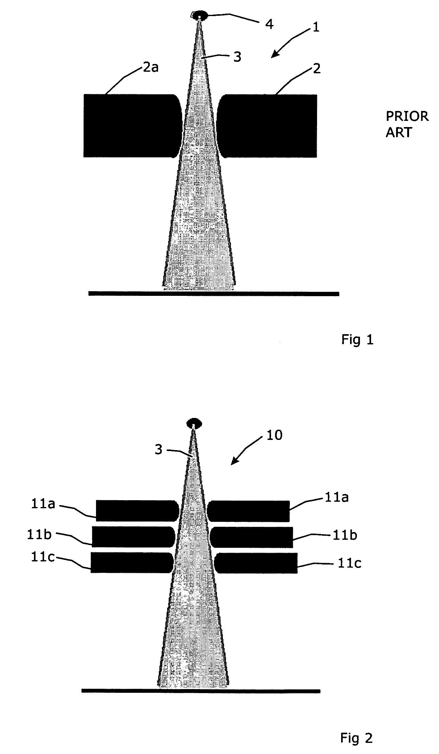
[0031]FIG. 1 shows the relevant part of a beam collimator 1 of conventional design. The collimator 1 comprises a set of a pair of multi-leaf banks 2, 2a disposed in a plane orthogonal to the direction of the X-ray or other beam 3 exiting from the aperture 4.

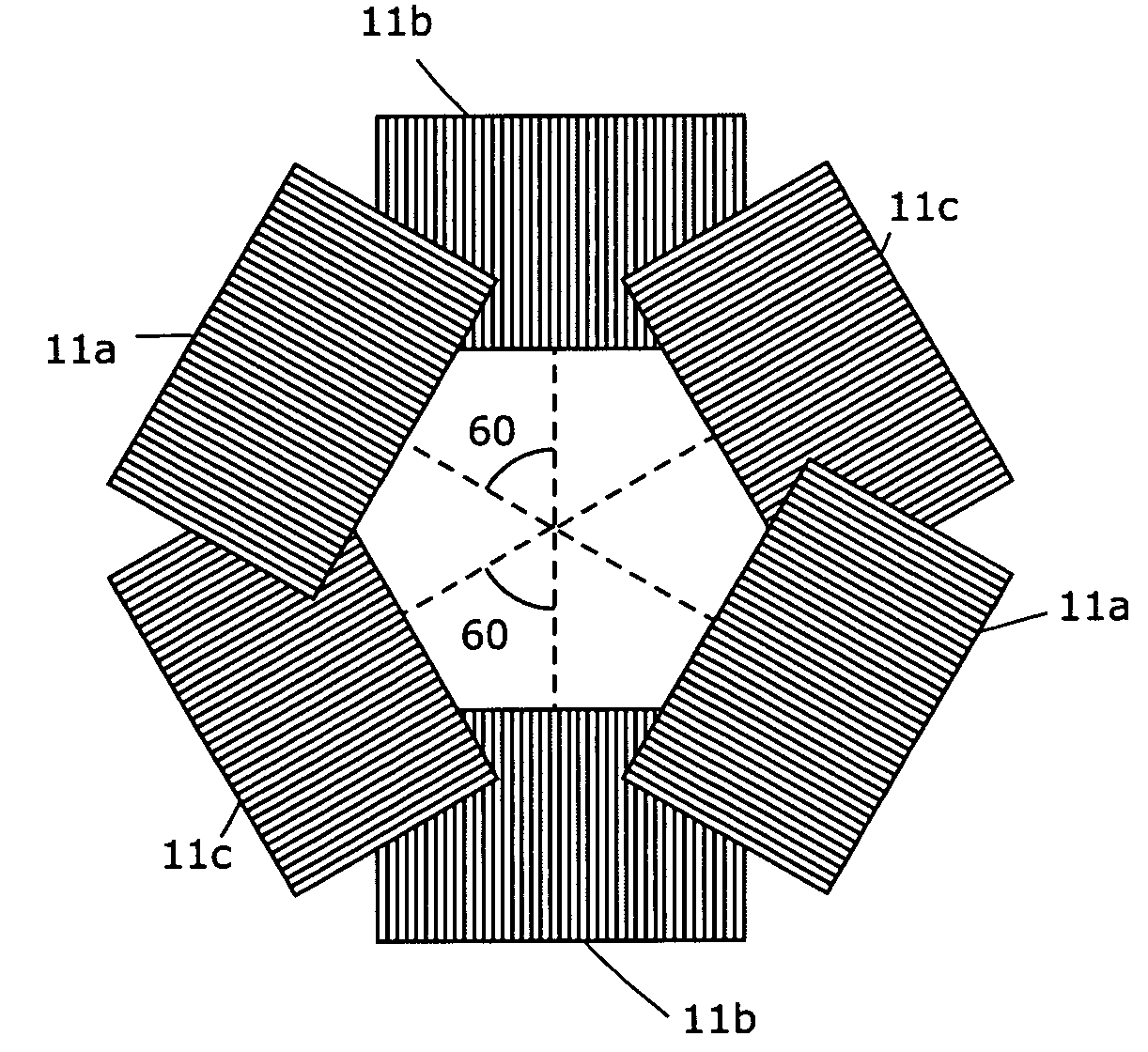
[0032]FIG. 2 shows the collimator 10 according to the present invention, in a corresponding vertical plane (i.e. in the direction of the beam 3) to FIG. 1 of the conventional type of collimator. The collimator comprises three multi-leaf sets, 11a, 11b and 11c, each set comprising a multi-leaf bank disposed on either side of the X-ray beam 3, and each disposed in a row in the vertical section. What is not visible in FIG. 2 is that the three banks are arranged in different orientations, such as with their leaf direction at 60° to each other.

[0033]FIG. 10 shows a top view of the multi-leaf collimator 10 of FIG. 2, wherein FIG. 10 illustrates an example of acute angles of 60 degrees between leaf directions of the sets 11a, 11b and be...


PUM


Abstract

A multi-leaf collimator is disclosed which alleviates the problems of inter-leaf leakage and pixellation. The collimator comprises a first multi-leaf collimator set, a second multi-leaf collimator set at an acute angle to the first, and a third multi-leaf collimator set at an acute angle to the second. Each multi-leaf collimator set will usually include a pair of leaf banks mutually opposed to each other. The acute angle between the first and the second multi-leaf collimator set is preferably the same as the acute angle between the second and the third set. A suitable angle is about 60°. To improve the penumbra characteristics, (i) the leaves of the multi-leaf collimator closest to the radiation source can be deeper in the direction of the radiation than the leaves of a multi-leaf collimator more distant from the radiation source, (ii) the leaves of the multi-leaf collimator furthest from the radiation source can be shallower in the direction of the radiation than the leaves of a multi-leaf collimator closer to the radiation source, (iii) the tips of the leaves of the multi-leaf collimators can be rounded (iv) the radius of curvature of the tips of the leaves of the multi-leaf collimator closest to the radiation source can be greater than the radius of curvature of the tips of the leaves of a multi-leaf collimator more distant from the radiation source, and (v) the radius of curvature of the tips of the leaves of the multi-leaf collimator furthest from the radiation source can be less than the radius of curvature of the tips of the leaves of a multi-leaf collimator closer to the radiation source. In general, it is also preferred that the first multi-leaf collimator is closest to the radiation source, the third multi-leaf collimator is furthest from the radiation source, and the second multi-leaf collimator is between the first and third multi-leaf collimators.

Description

FIELD OF THE INVENTION[0001]The present invention relates to a multi-leaf collimator.BACKGROUND ART[0002]Multi-leaf collimators (MLC) are used (principally) in the field of radiotherapy. A beam of radiation is directed toward a patient and must be collimated to fit the shape of the area to be treated. It is important to ensure that the dose in the areas outside that shape is as low as possible, but also that the whole area is treated. If areas are left untreated then the likelihood of recurrence is increased, whereas if non-treatment regions are irradiated then damage will be caused to healthy tissue resulting in greater side effects and longer recovery times after treatment.[0003]As the treatment area is rarely rectilinear, multi-leaf collimators are employed. These comprise an array of finger-shaped leaves of a radiation-absorbing material, each disposed in a parallel relationship and each able to move longitudinally relative to the others. By moving each leaf to a selected positi...

Claims


Application Information

Patent Timeline
Patent Type & Authority Patents(United States)
IPC IPC(8): G21K1/02A61N5/10G21K1/04
CPCA61N5/1042G21K1/046G21K1/04G21K1/025
Inventor TOPOLNJAK, RAJKOVAN DER HEIDE, UULKELAGENDIJK, JAN
Owner ELEKTA AB
Why Eureka
Try Eureka