Control of gas turbine for catalyst activation

a technology of catalyst activation and gas turbine, which is applied in the ignition of turbine/propulsion engine, engine starter, lighting and heating apparatus, etc., can solve the problems of pilot alone being unable to sustain stable combustion, producing undesired nox emissions, and being typically piloted

Inactive Publication Date: 2006-08-29
SIEMENS ENERGY INC
View PDF18 Cites 19 Cited by
  • Summary
  • Abstract
  • Description
  • Claims
  • Application Information

AI Technical Summary

Problems solved by technology

However, the LCL technique requires precise control of fuel and air volumes and may require the use a complex preburner to bring the fuel / air mixture to lightoff conditions.
One problem with the use of a pilot, however, is that the pilot is typically a diffusion-type flame producing undesired NOx emissions.
In addition, at a certain point during startup loading, such as at 50% of a base load, the pilot alone may not be able to sustain stable combustion.
Consequently, the catalyst needs to be activated before reaching a point of loading wherein the pilot may be unable to sustain stabilized combustion.
For example, in older gas turbines having comparatively lower compression ratios, or in a relatively cold ambient temperature environment, it may take longer for the compressor exit gas temperature to reach a catalyst activation temperature.
As a result, pilot stabilized combustion in the downstream combustion zone may become unstable before catalytic combustion can be activated.

Method used


Image

  • Control of gas turbine for catalyst activation
  • Control of gas turbine for catalyst activation
  • Control of gas turbine for catalyst activation

Examples


Embodiment Construction

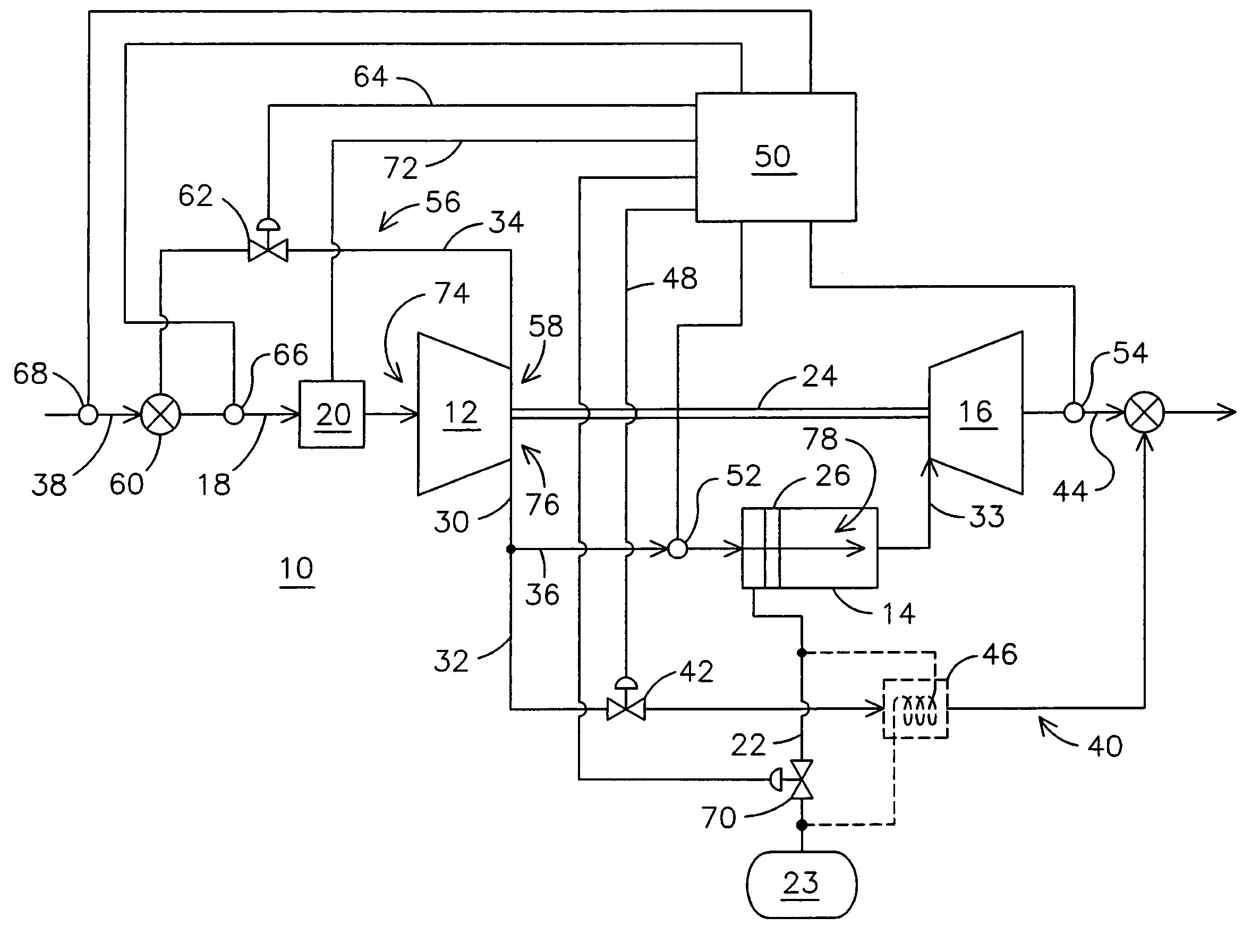
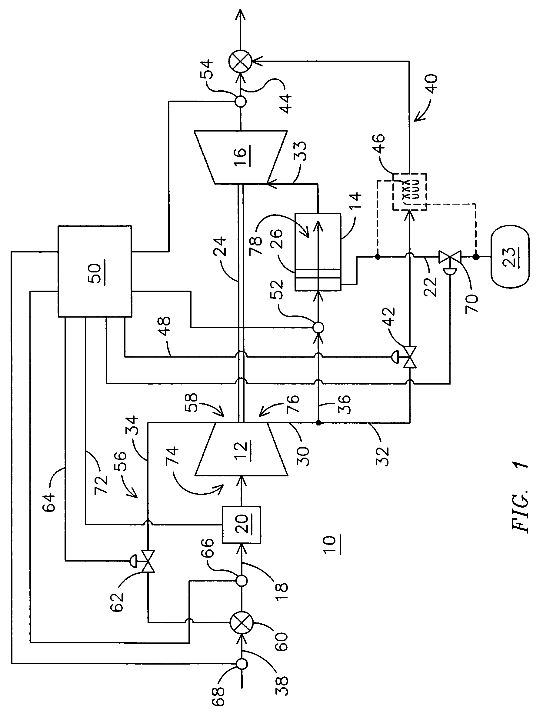
[0008]FIG. 1 is a functional diagram of a catalytic gas turbine 10. Major components of the gas turbine 10 include a compressor 12, a catalytic combustor 14, including a catalyst 26, and a turbine 16. The gas turbine 10 receives inlet air 18 through a set of inlet guide vanes 20. The inlet air 18 is compressed by compressor 12 and delivered to combustor 14, where it is used to combust a flow of fuel 22 from a fuel source 23 to produce hot combustion gas 33. The hot combustion gas 33 is delivered to turbine 16 where it is expanded to develop shaft power. Typically, the turbine 16 and compressor 12 are connected to a common shaft 24. The aforementioned components of the gas turbine 10 are fairly typical of those found in the prior art, and other known variations of these components and related components may be used in other embodiments of the present invention.

[0009]In a typical catalytic gas turbine startup procedure, the catalyst 26 remains inactive until the temperature of the air...


PUM


Abstract

A catalytic gas turbine includes a compressor, a catalytic combustor, a turbine, and a flow path conducting a bypass portion of the compressed air around the combustor and turbine. A method of operating the catalytic gas turbine to activate a catalyst in the catalytic combustor includes opening an inlet guide vane upstream of the compressor to a position to produce an increased volume of compressed air. The increased volume exceeds a volume of compressed air needed to support combustion. A bypass portion of the compressed air is extracted and directed around the combustor and turbine. The method may also include extracting a recirculation portion of the compressed air and directing the recirculation portion into the inlet of the compressor.

Description

FIELD OF THE INVENTION[0001]This invention relates generally to catalytic gas turbine operation, and more particularly to a method of controlling airflows in the gas turbine to achieve activation of a catalyst.BACKGROUND OF THE INVENTION[0002]It is known to use catalytic combustion in gas turbines to reduce NOx emissions. Catalytic gas turbines may include a compressor, a catalytic combustor, and a turbine. Typically, a catalyst is provided in an upstream portion of the catalytic combustor to catalytically accelerate a combustion process, thereby allowing combustion to occur at lower temperatures for reducing NOx formation. To initiate the catalytic combustion process, the catalyst must first be heated to an activation temperature. One such catalytic combustion technique, known as lean catalytic, lean burn (LCL) combustion, involves completely mixing fuel and air to form a lean fuel mixture that is passed over a catalytically active surface prior to introduction into a downstream co...

Claims


Application Information

Patent Timeline
Patent Type & Authority Patents(United States)
IPC IPC(8): F02C9/16F23R3/40F02C9/18F02C9/22
CPCF02C9/18F23R3/40F02C9/22F05D2260/20
Inventor LASTER, WALTER RAYBANDARU, RAMARAO V.BAER, JOAN MAE
Owner SIEMENS ENERGY INC
Why Eureka
Try Eureka