Method and apparatus for intelligently setting dead time

a dead time and intelligent technology, applied in the direction of electric variable regulation, process and machine control, instruments, etc., can solve the problems of significant dead time loss, high power loss penalty for significant overlap, and translates into, so as to minimize the overall converter power loss, minimize duty factor, and cost effective and convenient

Active Publication Date: 2006-08-29
INFINEON TECH AMERICAS CORP
View PDF12 Cites 84 Cited by
  • Summary
  • Abstract
  • Description
  • Claims
  • Application Information

AI Technical Summary

Benefits of technology

[0037]With PLMDT, the dead time is varied in such a manner so as to minimize overall converter power losses. Several means are available for monitoring power loss, including monitoring combinations of input and output voltage and current. If input and output voltage are fixed, only current monitoring is required and if averaging techniques are applied, only input current need be measured. The most cost effective and convenient means, however, is to use control switch duty factor as a relative gauge of power losses. When dead time is adjusted to minimize duty factor, converter power losses will also be minimized. In one implementation, the error amplifier output is used in place of the duty factor. This is possible because the error signal is the modulation input to the PWM stage. Consequently, the PWM duty factor is proportional to the error voltage.
[0038]In one embodiment of the present invention, saved dead-time values from PLMDT are used so that in the future, power loss can be minimized without taking the time according to the PLMDT technique at that instant to search for optimum values. Although it is preferred to use PLMDT, other techniques for updating the stored dead time value can also be employed.
[0041]A preferred option from a performance standpoint is to have the mapping done at periodic intervals throughout the life of the product application. In this way, the optimum settings, once found, can be periodically updated. For example, periodically, the system can invoke PLMDT to determine new, optimized values which are then stored in memory.

Problems solved by technology

The power loss penalty for significant overlap is extremely high compared to the additional conduction losses occurring during dead time.
Still, dead time losses are significant; especially as converter operating frequency is increased.
At the above conditions, this translates into an additional 27 mW power loss per nanosecond of dead time.
Two switching edges per cycle of 20 ns dead time each results in an additional 1.088 watts of loss in the synchronous switch, a 20% increase in losses for that component.
Using a Schottky diode in parallel with the MOSFET will reduce that figure by 30%-to-40%, but at additional cost and component count.
This amounts to cross conduction and causes additional losses in the control FET.
Consequently, when no crossover is achieved with the worst case components at the worst case conditions, dead time with best case components and conditions is excessive.
This results in excessive wasted power loss.
Most of the problem with adaptive dead time is the time required to switch the FETs off and on.
In terms of power supply operation, this optimization takes a long time—tens of milliseconds.
That means that in fast load transient environments, the PLMDT operation cannot keep up with power supply changes.
This works very well, but still falls short of having the exact right dead time for each current.
This means the off delay is increased, since the dead time is decreased.
However, results are a compromise based on average circuit conditions rather than an optimum based on exact instantaneous operating conditions.

Method used


Image

  • Method and apparatus for intelligently setting dead time
  • Method and apparatus for intelligently setting dead time
  • Method and apparatus for intelligently setting dead time

Examples


Embodiment Construction

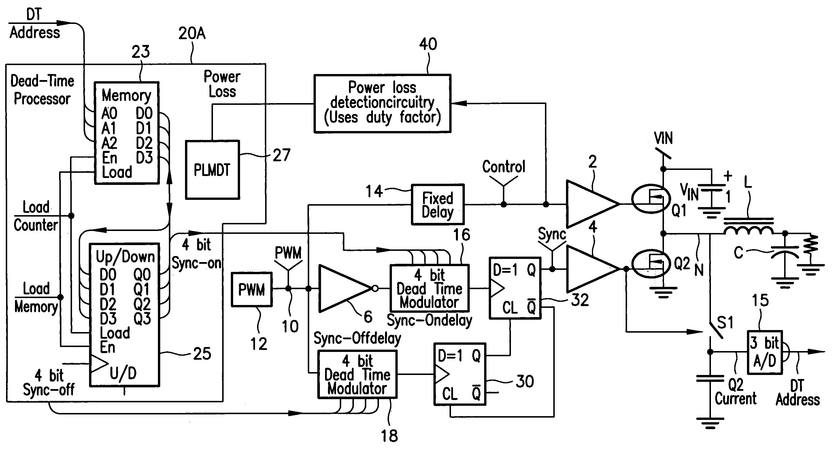
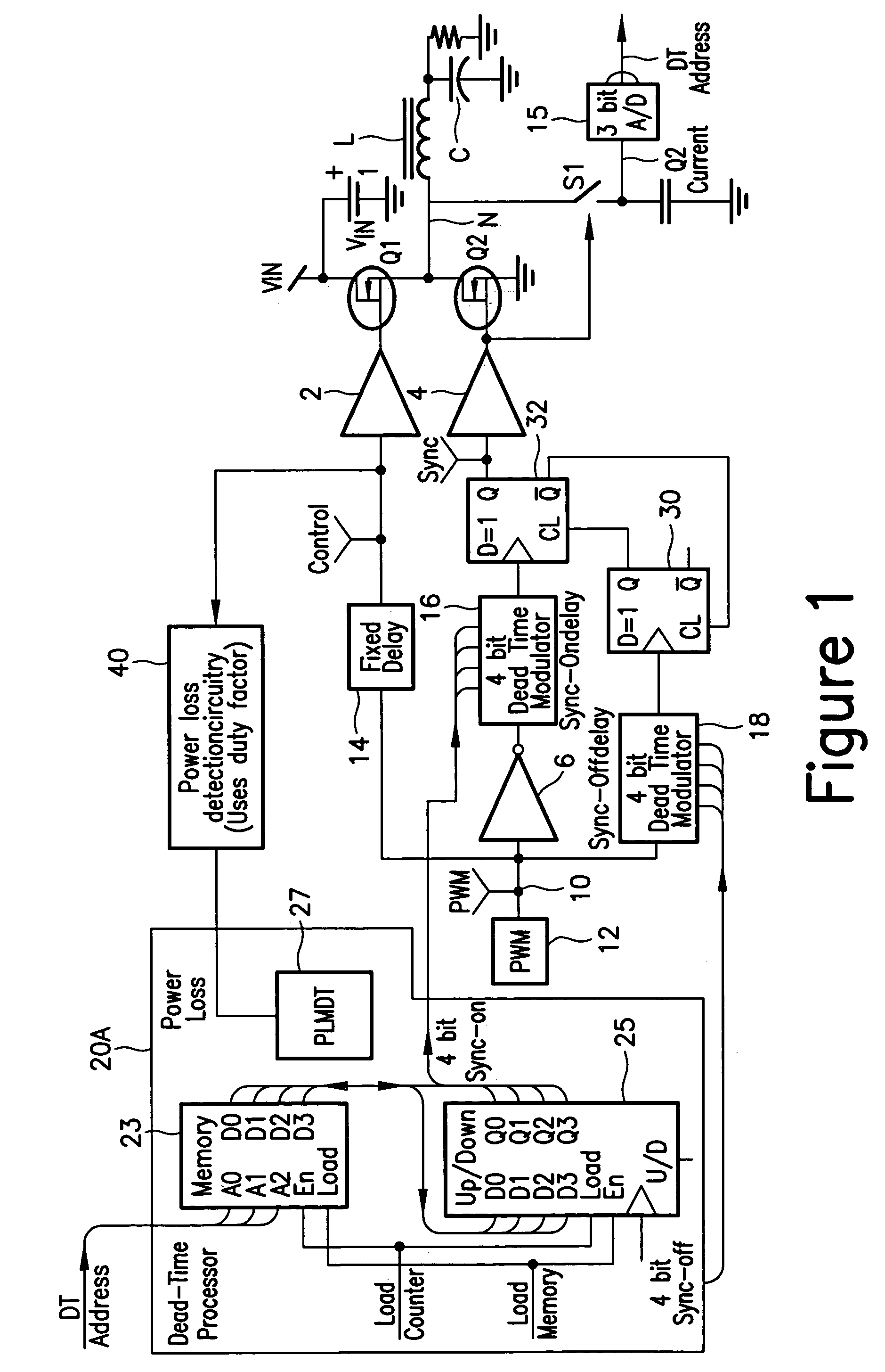
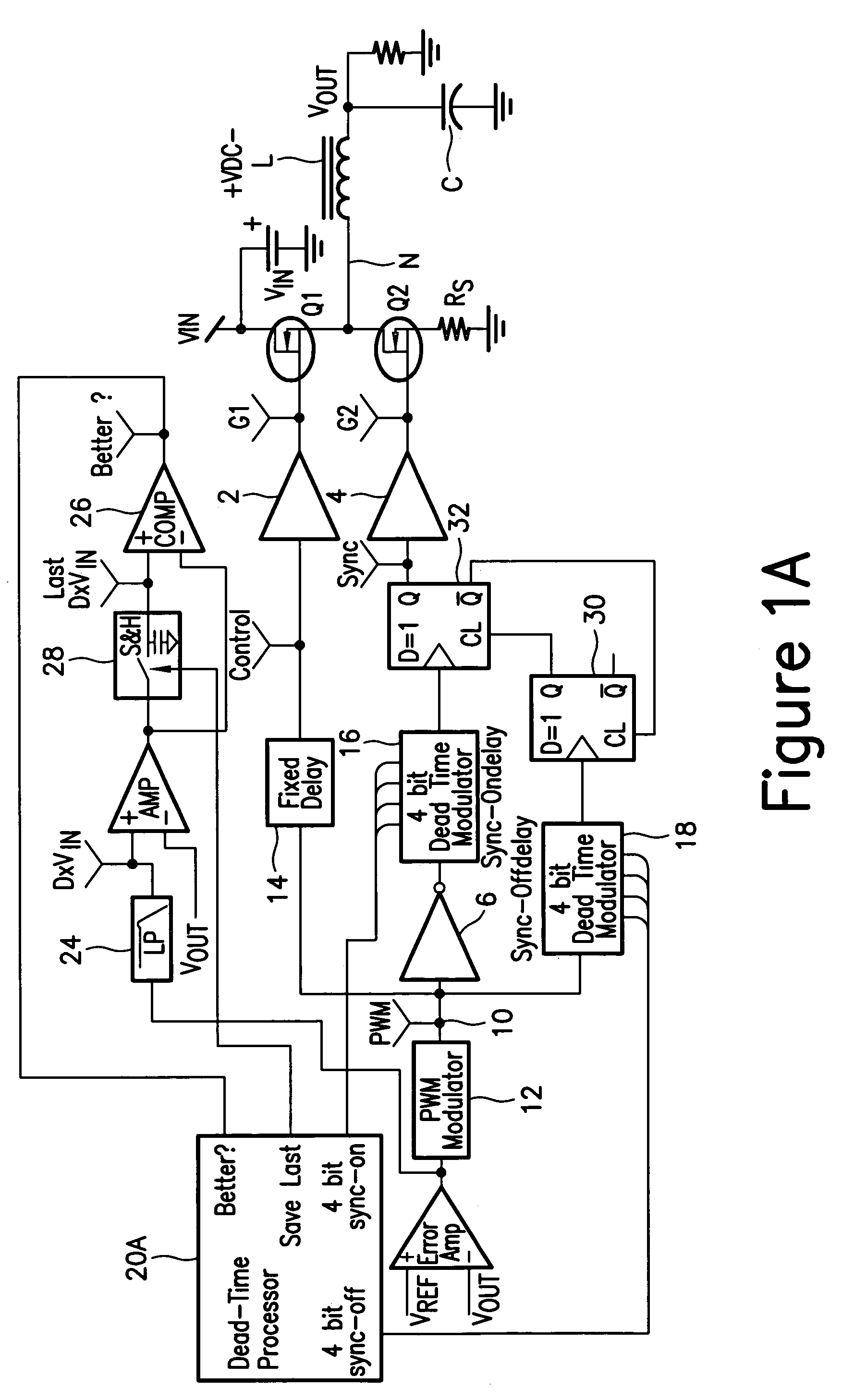
[0050]Turning again to the drawings, FIG. 1 shows one possible implementation of a converter circuit implementing the intelligent dead time (IDT) method according to the present invention. Many other implementations are possible because the essential element of the present invention is that optimum dead time is “memorized” over the power supply operating range, and then “recalled” when needed later. Conditions monitored by the system will vary from one implementation to another, but may include: Input voltage, output current (e.g., synchronous switch current), and MOSFET driver temperature.

[0051]FIG. 1 shows one possible implementation of the present invention which combines digital and analog circuitry. Others are possible and most blocks and functions can be implemented with digital circuitry as well as analog.

[0052]FIG. 1 shows a DC—DC converter circuit that has been modified to incorporate the technique according to the present invention to intelligently set dead time to minimiz...


PUM


Abstract

Apparatus for setting dead time between ON times of two series connected switches of a power converter circuit connected across a supply potential, the apparatus comprising a circuit for monitoring a power converter circuit parameter and providing an output corresponding to the circuit parameter; a memory addressed by a signal related to the output of the monitoring circuit, the memory having values stored therein related to the dead times and associated with values of the circuit parameter; a processor providing an output of the memory associated with the value of the circuit parameter to set the dead time corresponding to the stored value in the memory, and a dead time implementing stage for implementing the dead time in accordance with the output of the memory.

Description

CROSS REFERENCE TO RELATED APPLICATION[0001]This application claims the benefit and priority of U.S. Provisional Patent Application Ser. No. 60 / 585,678 filed Jul. 6, 2004 and entitled “Intelligent Dead Time”, the entire disclosure of which is incorporated herein by reference.BACKGROUND OF THE INVENTION[0002]The present invention relates to power supplies and in particular to voltage converters employing two controlled switches, one of which operates as a synchronous rectifier. The two switches are generally controlled so that both switches are never on at the same time. A “dead time” is provided between the on-times of the two switches to prevent cross conduction across the DC voltage supply between which the two switches are connected in series.[0003]Synchronous rectification has been widely adopted for use in low voltage output converters of various topologies: Buck, boost, fly back, and forward. By substituting a MOSFET switch for a silicon or Schottky diode, rectification losses...

Claims


Application Information

Patent Timeline
Patent Type & Authority Patents(United States)
IPC IPC(8): G05F1/40
CPCH02M3/1588H02M2001/0012Y02B70/1491Y02B70/1466H02M2001/0048H02M1/0012H02M1/0048Y02B70/10G05F1/40H02M3/335
Inventor BROWN, JAMES S
Owner INFINEON TECH AMERICAS CORP
Why Eureka
Try Eureka