Internal combustion engine

a combustion engine and combustion chamber technology, applied in the field of engines, can solve the problems of not being practicable to add engine oil for lubrication, and achieve the effect of easy glid

Active Publication Date: 2006-09-05
CUMMINS ENGINE CO LTD
View PDF16 Cites 6 Cited by
  • Summary
  • Abstract
  • Description
  • Claims
  • Application Information

AI Technical Summary

Benefits of technology

[0004]The present invention seeks to provide an arrangement that permits the dipstick to be securely held in place without requiring the additional cost and complexity of forming special locking elements on the body of the engine and on the cap of the dipstick.
[0012]the cap comprises a spigot rotatably received in the mouth of the hole and a flange extending radially outwards from the spigot to cover the mouth of the hole, the flange being non-circular so that by rotation of the cap relative to the hole, a radially projecting portion of the edge of the flange may be selectively engaged beneath the overhanging lip to prevent axial displacement of the cap and the dipstick relative to the engine body.
[0013]In a preferred embodiment of the invention, the engine body is formed of a cylinder block and a separate cast oil sump secured to the cylinder block, the hole for the dipstick is formed in the oil sump casting and the overhanging lip is formed by a part of the cylinder block, or of a gasket disposed between the cylinder block and the oil sump, that projects laterally beyond the oil sump. It will be noted that the face of the cylinder block mating with the oil sump is always machined flat and any gasket used to seal between cylinder block and the oil sump will also have a smooth flat surface. Consequently, when the engine is formed in this manner, the overhanging lip will present a smooth face past which the edge of the flange on the cap can glide easily without requiring an additional machining step.

Problems solved by technology

In agricultural vehicles, it is not practical to add engine oil for lubrication by pouring it into a valve cover at the top of the engine.

Method used


Image

  • Internal combustion engine
  • Internal combustion engine

Examples


Embodiment Construction

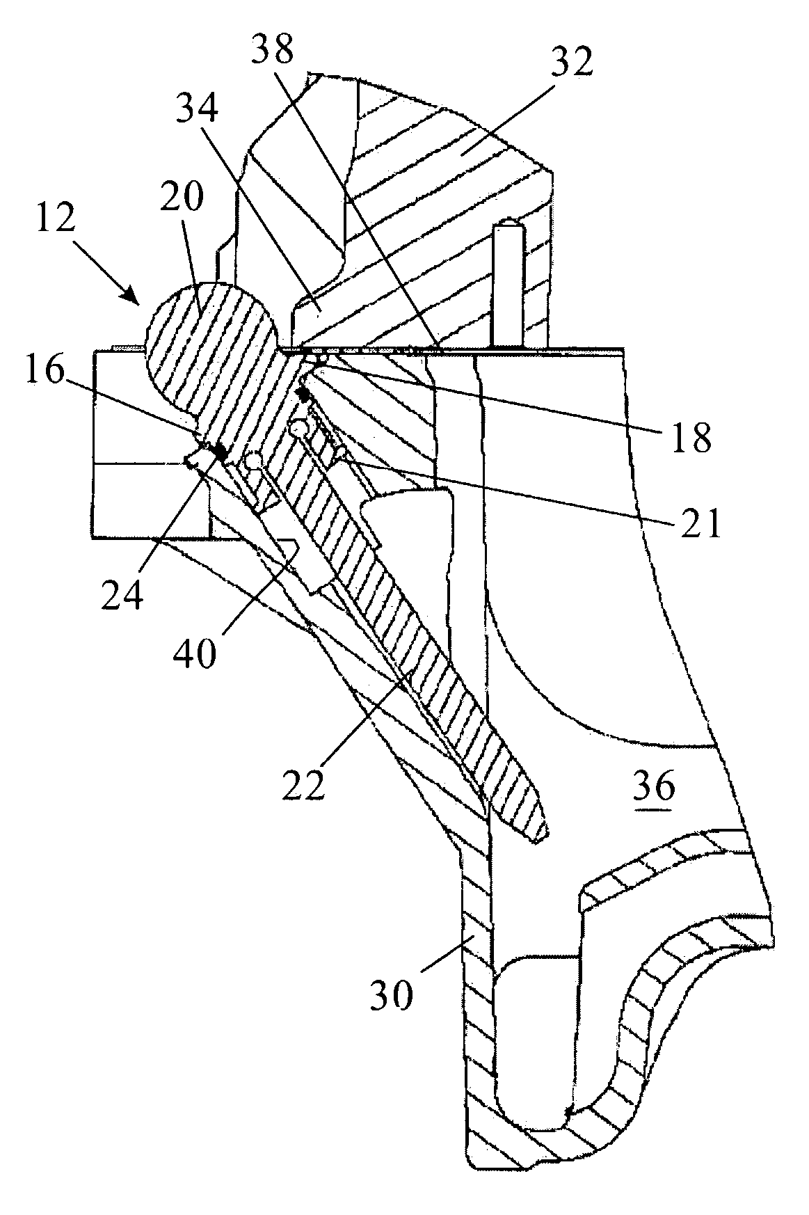
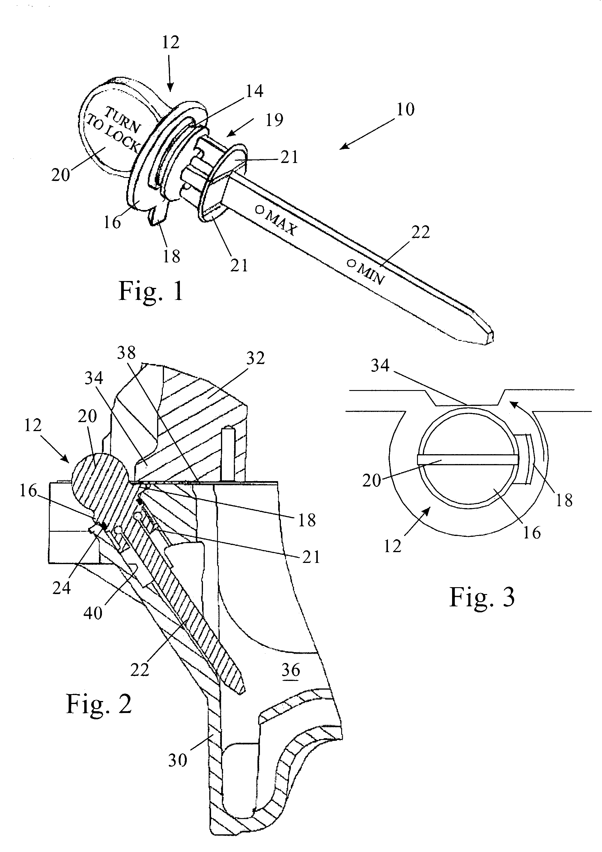
[0022]The combined dipstick and oil filler cap 10 shown in the drawings comprises a dipstick portion 22 formed integrally with a cap 12, the two being formed as a one-piece injection moulded component. The cap 12 comprises a cylindrical spigot 19 dimensioned to fit in the oil filler hole, designated 40 in FIG. 2. The upper part of the spigot 19 is formed with an annular groove 14 which receives an O-ring 24 that seals against the cylindrical wall of the filler hole 40. The lower end of the spigot 19 has two resilient claws 21 that frictionally grip the filler hole so that the spigot fits snugly in the filler hole 40.

[0023]A flange 16 extending radially from the spigot 19 covers the mouth of the hole. The flange 16 is non-circular, being provided with a radially projecting locking finger 18. Additionally, the cap has a projecting disc 20 by means of which the cap can be manually gripped and turned.

[0024]The body of the engine is formed with an overhanging lip 34 beneath which the pro...


PUM


Abstract

An engine is described having a hole for a dipstick which is closed by a cap from which the dipstick depends. The engine body is formed with an overhanging lip adjacent the mouth of the hole, and the cap comprises a spigot rotatably received in the mouth of the hole and a flange extending radially outwards from the spigot to cover the mouth of the hole. The flange is non-circular so that by rotation of the cap relative to the hole, a radially projecting portion of the edge of the flange may be selectively engaged beneath the overhanging lip to prevent axial displacement of the cap and the dipstick relative to the engine body.

Description

FIELD OF THE INVENTION[0001]The present invention relates to an engine having an oil dipstick and is concerned in particular with the retention of the dipstick on the body of the engine.BACKGROUND OF THE INVENTION[0002]In agricultural vehicles, it is not practical to add engine oil for lubrication by pouring it into a valve cover at the top of the engine. For this reason, it is known to use the access hole for the dipstick as the filler hole for adding oil to the engine. When the dipstick access hole is made larger to permit oil to be poured into the engine through it, there is an increased tendency for the dipstick to be ejected by the crankcase pressure acting on the cap closing off the filler hole.[0003]An oil filler tube assembly for an internal combustion engine that mitigates this problem is disclosed in U.S. Pat. No. 5,022,495. This assembly includes a tube having a lower end communicating with the crankcase of the engine and an open upper end that is closed by a cap. The und...

Claims


Application Information

Patent Timeline
Patent Type & Authority Patents(United States)
IPC IPC(8): G01F23/04F01M11/12
CPCG01F23/04F01M11/12
Inventor KETTLE, RICHARDBANCHIO, ALDO
Owner CUMMINS ENGINE CO LTD
Why Eureka
Try Eureka