
Adjustable rear spacer wall assembly for a vending machine

Inactive Publication Date: 2006-09-05
CRANE MERCHANDISING SYSTEMS
View PDF28 Cites 6 Cited by
  • Summary
  • Abstract
  • Description
  • Claims
  • Application Information

AI Technical Summary

Benefits of technology

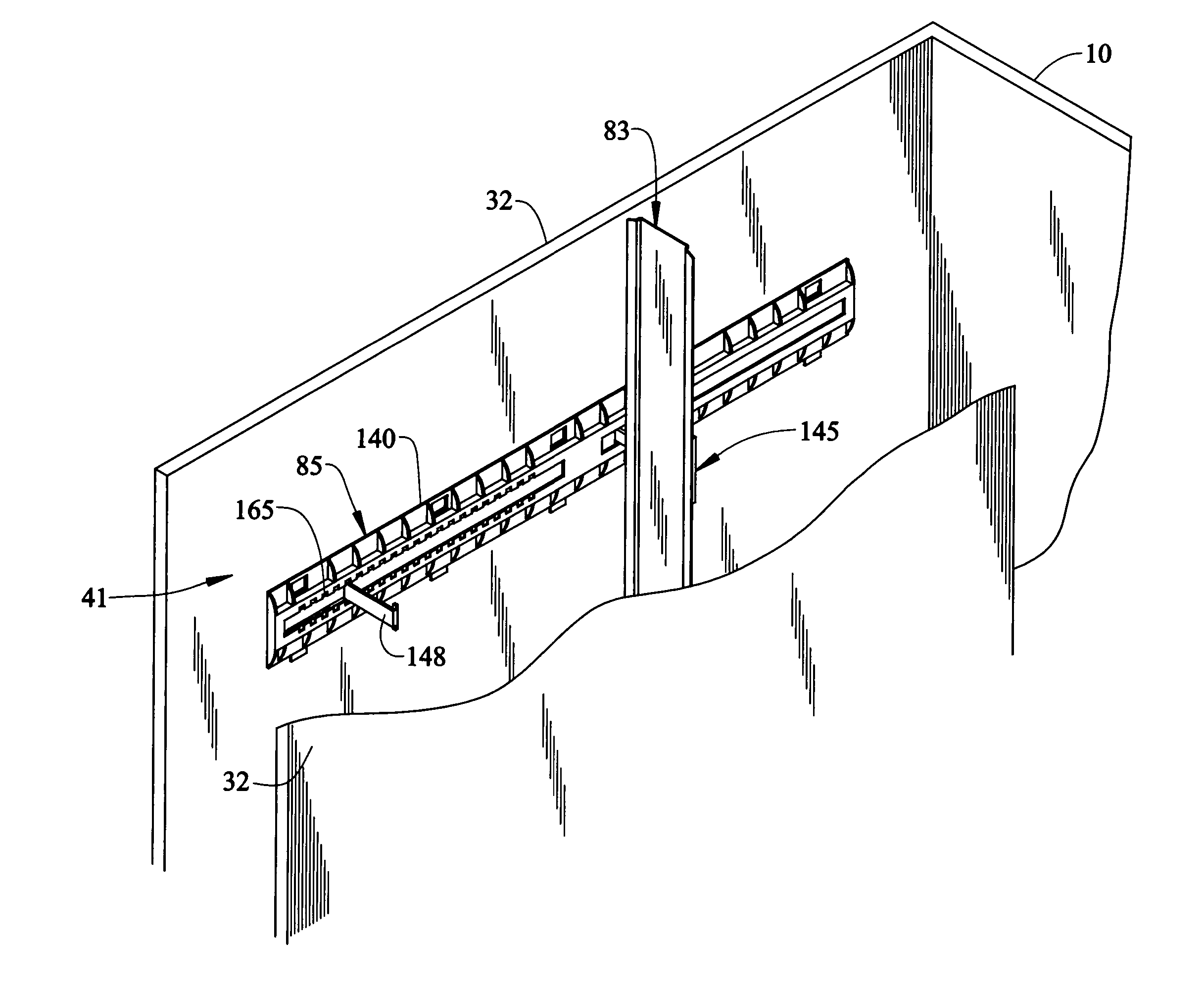
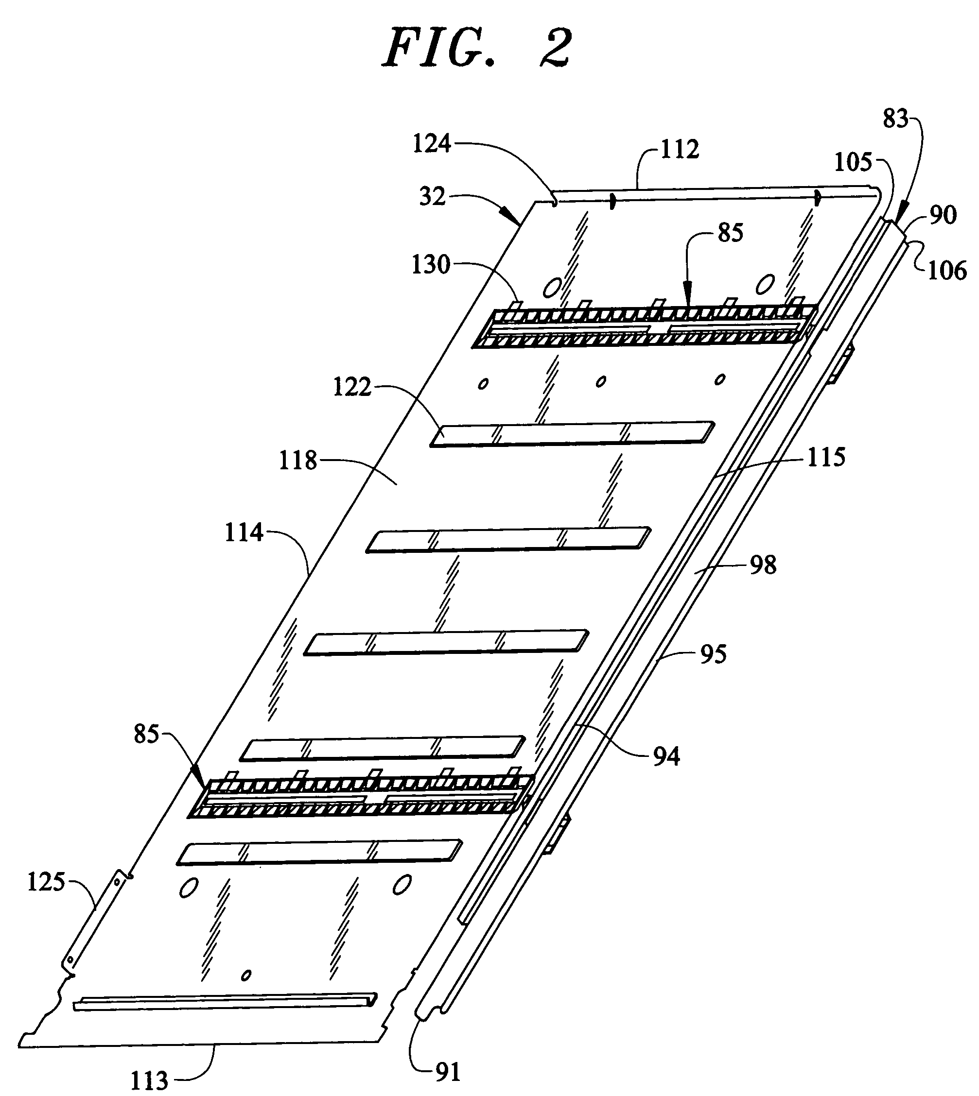
[0010]The guide arm, which is movable along the guide channel defining member, is a long, narrow piece that slidably connects to the guide channel defining member. The guide latch is attached to a first end of the guide arm and the rear spacer bracket is attached to a second end of the guide arm. The rear spacer wall is attached to the spacer brackets of the upper and lower adjustable channel assemblies and may be adjusted by lifting the guide latch from a locked position, wherein it is substantially parallel to the guide arm, to an unlocked position. When the guide latch is in an unlocked position, the guide arm may be positioned by pushing or pulling the guide latch until the guide arm is in the desired position. By moving the guide latch, the guide arm forces the rear spacer wall in the same direction. In addition, the upper and lower channel assemblies are independently adjustable to maximize the ease of adjustment. With this arrangement, a delivery person can change the position of the rear spacer wall simply and quickly to accommodate different sized product containers in the stack areas.

Problems solved by technology

The product spacers hang from the column walls and are often difficult to reposition.
However, the adjustable retainer assembly does not provide a quick method of adjusting the retainers.
This method of repositioning the retainers is considered undesirable and tedious.

Method used


Image

  • Adjustable rear spacer wall assembly for a vending machine
  • Adjustable rear spacer wall assembly for a vending machine
  • Adjustable rear spacer wall assembly for a vending machine

Examples


Embodiment Construction

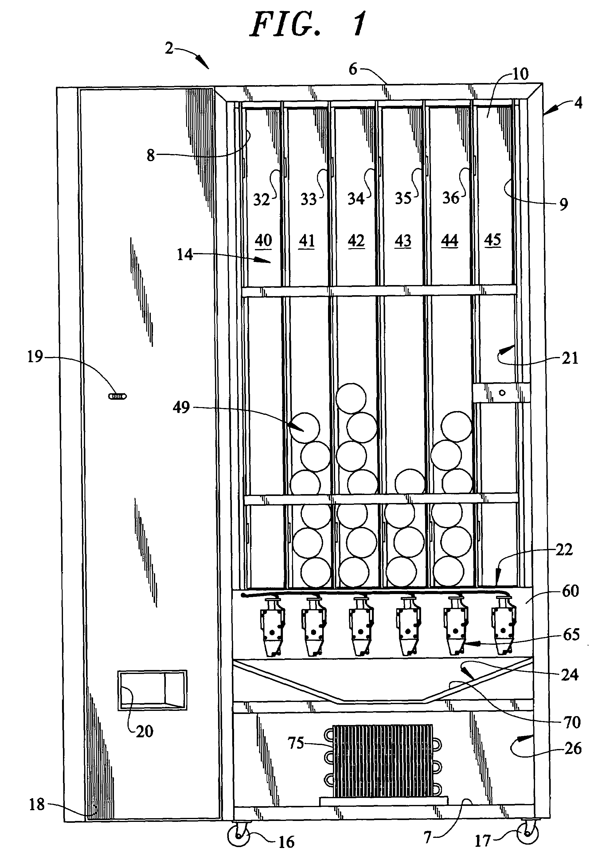
[0024]With initial reference to FIG. 1, a vending machine 2 includes a cabinet frame 4 having top, bottom, side and rear walls 6–10 that collectively define a central cavity 14. In a manner known in the art, a first pair of wheels or casters 16 and 17 are secured to a front edge portion of bottom wall 7 to facilitate the positioning of vending machine 2. Of course it should be realized that a second pair of wheels (not shown) are also arranged on a rear portion of bottom wall 7. A door 18 is pivotally mounted to cabinet frame 4 to selectively enable access to central cavity 14 in order to load various product containers or other commodities into vending machine 2. Door 18 is provided with a locking mechanism, shown in the form of a threaded rod 19, to retain door 18 in a closed position so as to prevent pilfering of the commodities from central cavity 14. Door 18 is also provided with an opening 20 to enable a consumer to remove a vended product container or other commodity from ven...


PUM


Abstract

A vending machine includes an adjustable channel assembly for varying the depth of a product stack area within the vending machine. Preferably two adjustable channel assemblies are mounted to a column wall to support a rear spacer wall that defines a back portion of the stack area. The rear spacer wall is selectively movable fore-to-aft in order to permit the stack area to be customized in order to accommodate various sized bottles and cans.

Description

CROSS-REFERENCE TO RELATED APPLICATIONS[0001]The present application claims benefit of U.S. Provisional Patent Application Serial No. 60 / 415,763 entitled “ADJUSTABLE REAR SPACER WALL ASSEMBLY FOR A VENDING MACHINE” filed on Oct. 4, 2002.BACKGROUND OF THE INVENTION[0002]1. Field of the Invention[0003]The present invention pertains to the art of vending machines and, more particularly, to an adjustable rear spacer wall assembly which enables a compartment to be readily adapted to store bottles and cans of various sizes.[0004]2. Discussion of the Prior Art[0005]Vending machines for dispensing cans and bottles typically include multiple compartments for storing the cans and bottles in columns. Each compartment is suitable for storing a depth of one or more cans or bottles. An adjustable product spacer that allows the vending of a variety of differently sized cans or bottles is often located at the rear of each compartment. The product spacers hang from the column walls and are often dif...

Claims


Application Information

Patent Timeline
IPC IPC(8): B65G59/00B65H3/44G07F11/00G07F11/08G07F11/10
CPCG07F11/007G07F11/10G07F11/08
Inventor KELLY, PAUL HAYWARDLEWIS, ARON PHILIPPOWELL, JOSHUA ROBERTRICHARDSON, EDMUND SCOTTSAMSON, JOHN T.
Owner CRANE MERCHANDISING SYSTEMS
Learn More