Pillow rack

a pillow rack and pillow technology, applied in the field of pillow racks, can solve the problems of too attractive pillows for bugs and pets, easy and rapid positioning of pillows, and easy collapse of frame members, and achieve the effect of reducing the risk of falling

Active Publication Date: 2019-07-30
WILLIAMS JUDITH A
View PDF46 Cites 3 Cited by
  • Summary
  • Abstract
  • Description
  • Claims
  • Application Information

AI Technical Summary

Benefits of technology

[0017]Desirably, when in the in use position, the upper frame portions are at an angle relative to the axis of rotation and form a cradle that will position the center of gravity, or weight of the combined stack, either generally above the axis of rotation about which the frame members rotate or slightly toward the wall, decreasing the potential for the rack to relatively rotate and become unstable.
[0018]Desirably, the respective frame members are connected in a scissors-like fashion such that when the rack is in the first position and not in use, the upper portions and the lower portions, respectively, are in substantially parallel juxtaposed facing relation with one another. The not in use mode provides a generally thin profile, is compact, and maximizes ease of storage.
[0024]Desirably, the rack having upper and lower ends of the two frame members abutted against a vertical room wall aids in supporting and stabilizing the pillow rack in the open position, resists rotational collapse of the frame members, enables a user to easily and rapidly position pillows in generally horizontally and vertically stacked relation, and increases the vertical height of the pillows that can be stacked using a smaller support rack. This is particularly helpful when the items being stacked might include first loading a bulky bedspread and the like on the supporting platform before adding the weight of more pillows provide by an upward vertical stack.
[0025]According to another preferred embodiment of this invention there is disclosed a foldable rack for storing pillows in vertically stacked relation, comprising: (a) a pair of generally rectangular and planar frame members each having, respectively, upper and lower ends, a pair of sides, and a central portion that divides the frame into an upper portion and a lower portion; (b) means for connecting the frame members together in a manner that the frame members rotate relative to an axis through the central portions from a not in use first position wherein the frame members are in generally parallel relation to one another and an open second position wherein the frame members form an X shape and the upper portions define an upwardly open cradle for receiving and supporting pillows in generally horizontal vertically stacked relation atop the pillows and the lower portions and their respective lower ends support the rack on a support surface; and (c) means for releasably locking the frame members in the open second position.
[0031]Desirably a pillow rack according to this invention is thin in design, can be stored in hanging relation in a closet rod in sandwiched relation between shirts or other garments hung on the rod, is deployed or stored rapidly when needed or not in use. Further, the rack keeps bedding clean and safe, off the floor, freeing up open space for bed-making, and eliminates piled high chairs, and dresser tops. The rack design enables the user to select various clean designs or decorating styles.

Problems solved by technology

As is usually the case, the pillows get tossed on the floor creating trip hazards or clutter until the bed is made up again.
This is also very annoying in guest bedrooms, since your guest may not know what to do with all those pillows and will throw them on the floor or atop furniture possibly damaging lamps or accidentally forcing items to the floor.
Worse still, the floor just makes the pillow too attractive to bugs and pets, possible stains, and other contamination.

Method used


Image

  • Pillow rack
  • Pillow rack
  • Pillow rack

Examples


Embodiment Construction

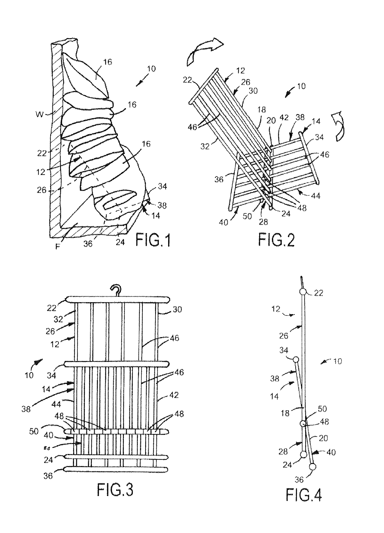
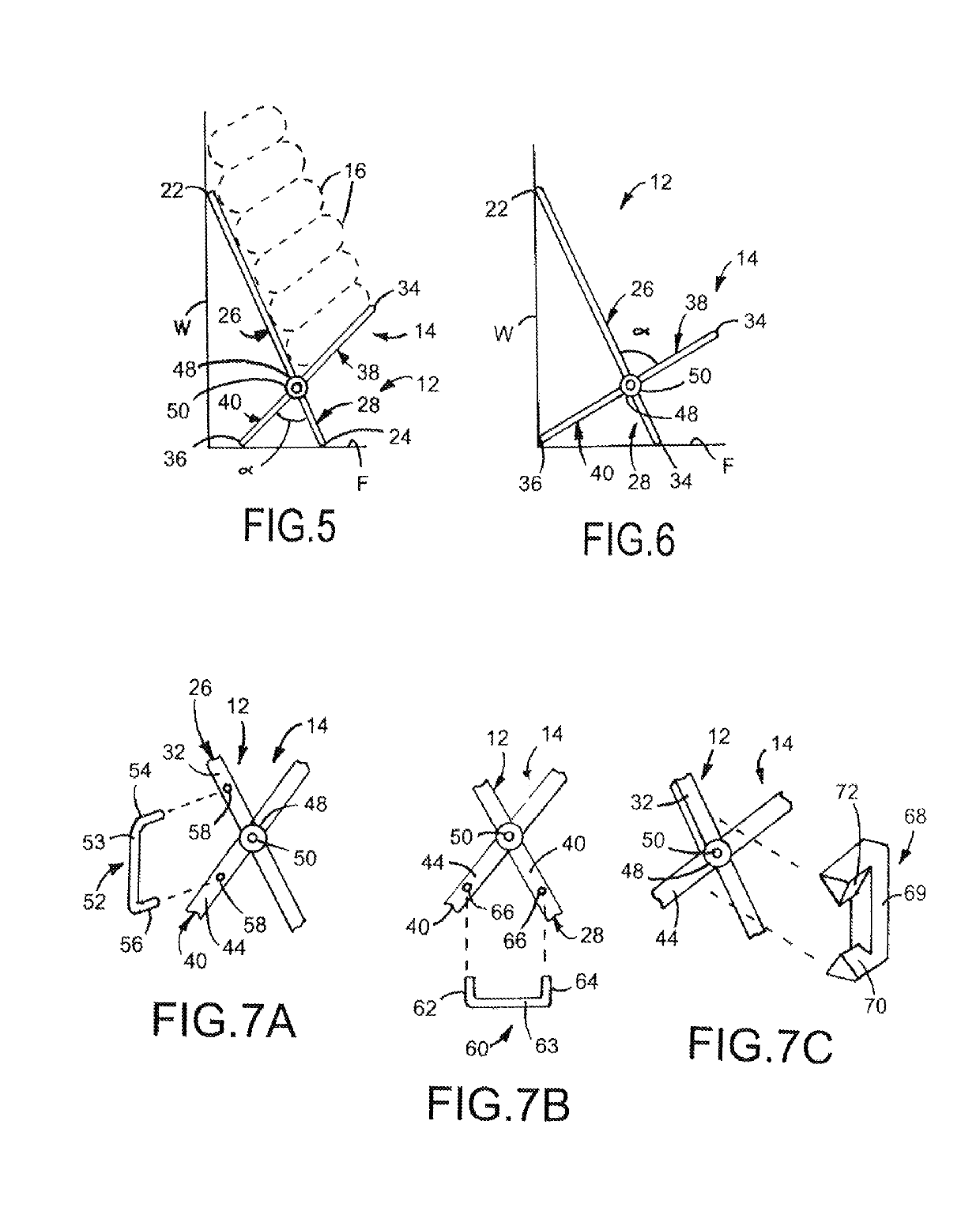
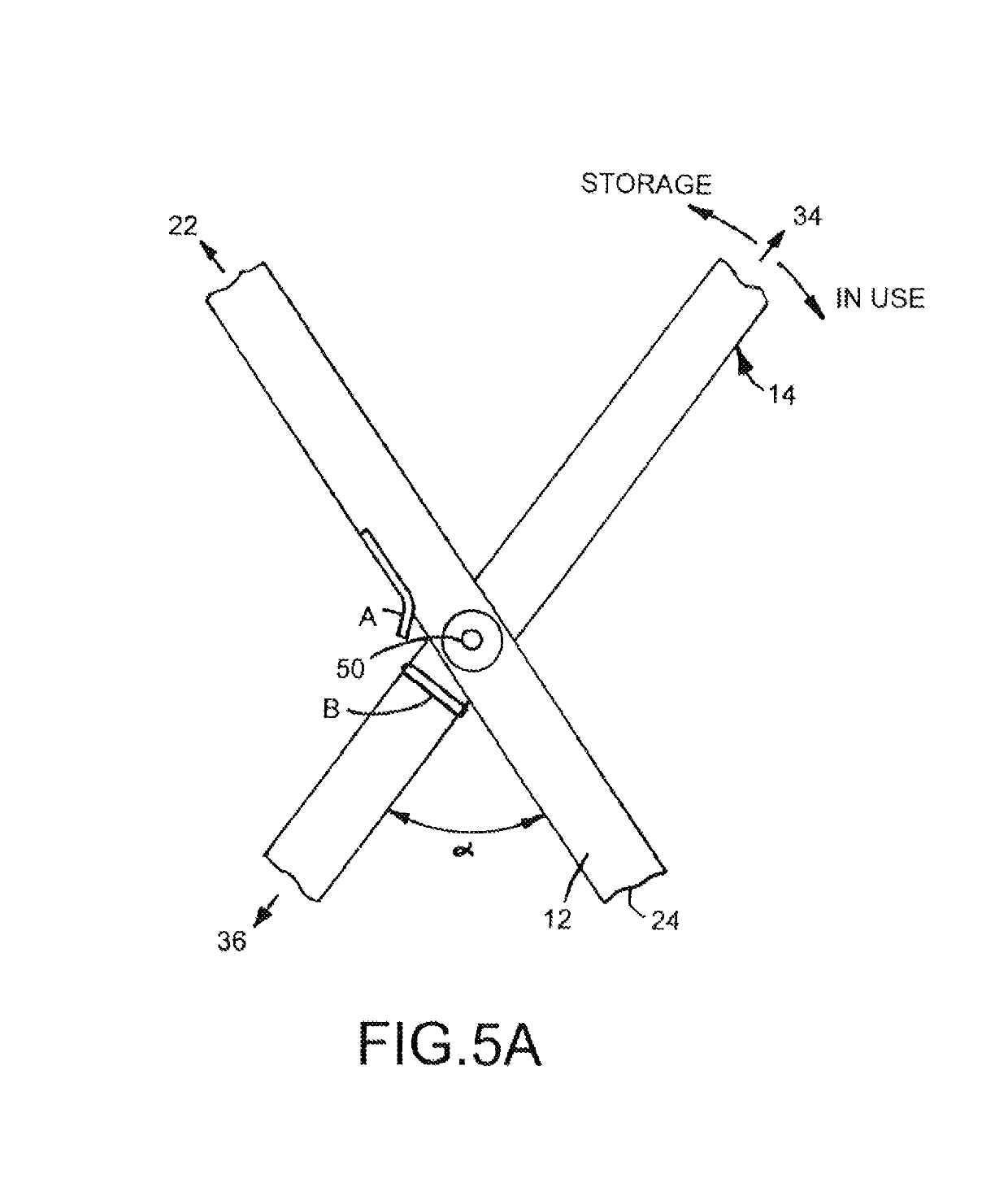
[0041]Turning now to the drawings, FIGS. 1-4 depict a pillow rack 10 for temporarily storing pillows, bedding, and like materials in a vertical stack when not in use and which provide easy access, such as in a bedroom when preparing the room for sleeping and turning down the bed. The pillow rack 10 includes a pair of frame members 12, 14 that rotate from a first position (FIGS. 3 and 4) when the rack 10 is not in use, the frame members 12, 14 are folded onto one another and the rack 10 is to be stored, into a second position (FIGS. 1 and 2) when the rack 10 is ready for use. In FIG. 1, the rack 10 is under the pillows and the frame members 12, 14 are shown by the phantom lines. FIGS. 5 and 6 are side elevation views showing arrangements of the pillow rack 10 positioned on a floor F and against a vertical wall W of the room.

[0042]FIGS. 1 and 5 show the pillow rack 10 wherein the frame members 12, 14 are in the in use position functioning to support the rack 10 against the floor F and...


PUM


Abstract

A foldable rack for storing pillows comprising a first and second frame member being generally planar and rectangular, each frame member including: (a) an upper end and a lower end defining a length; (b) opposing lateral sides connecting the upper end and the lower end defining a width; (c) a plurality of spaced apart rods extending from the upper end to the lower end, each rod having a hub disposed at a central portion, each hub having an axial bore therethrough, each axial bore in registry; and (d) a pin being received in the axial bore extending through each hub of each rod. The rack folds about the pin in a scissor-like fashion between a first not in use position where the first and second frame members fold into juxtaposed position and a second in use position where the first and second frame members intersect to form an X shape.

Description

CROSS-REFERENCE TO RELATED APPLICATIONS[0001]This application is a completion application of co-pending U.S. Provisional Patent Application Ser. No. 62 / 064,007, filed Oct. 15, 2014, for “Pillow Rack,” the entire disclosure of which is hereby incorporated by reference in its entirety including the drawings.BACKGROUND OF THE INVENTION[0002]1. Field of the Invention[0003]The present invention pertains to storage racks, and more particularly to a storage rack for storing pillows that comprises a pair of frame members that are connected to one another in a scissors like fashion and form a collapsed low profile form for easy storage when the rack is in a first position and not in use and rotate into a second position wherein the frame members form an X wherein the pillows are stacked vertically atop one another for easy accessible temporary storage when the pillows are not in use.[0004]2. Description of Related Art[0005]Throw pillows or accent pillows are great additions that will complet...

Claims


Application Information

Patent Timeline
Patent Type & Authority Patents(United States)
IPC IPC(8): A47B81/00A47B55/02A47B43/00A47F5/13
CPCA47B81/00A47F5/13A47B55/02A47B43/00
Inventor WILLIAMS, JUDITH A.
Owner WILLIAMS JUDITH A
Why Eureka
Try Eureka