
Front panel having push buttons formed integrally therewith

a technology of push buttons and front panels, applied in contact mechanisms, television systems, instruments, etc., can solve the problems of not being favorable as front panels for electrical equipment, unable to reduce components and assembly steps, and hardly reducing the manufacturing cost of front panels, so as to increase the push button push stroke and facilitate sliding

Inactive Publication Date: 2006-09-05
FUNAI ELECTRIC CO LTD
View PDF9 Cites 17 Cited by
  • Summary
  • Abstract
  • Description
  • Claims
  • Application Information

AI Technical Summary

Benefits of technology

The present invention provides a front panel for electrical equipment with push buttons formed integrally therewith, which requires no additional cover panel while being excellent in appearance, reduces the components and steps in assembling for cost reduction. The push buttons are linked to the front panel through a button supporting portion and a button arm, which allows for secure push stroke of the push button. The front panel also includes a bottom plate extending backward from the lower part of the face plate of the front panel with an opening formed by removing the upper part of the slidable core and a fence functioning as a static electricity shield. The plurality of push buttons are arranged in a row at appropriate intervals, and a unitary slidable core can be used that has a comblike structure with a plurality of upper parts branched, for easy sliding.

Problems solved by technology

However, the front panel to be constructed in such a manner requires increased components as well as increased steps in assembling, thus hardly reducing the manufacturing cost of the front panel.
However, either the front panel as shown in FIG. 7 or the molded panel as disclosed in the Japanese Patent Laid-open Publication No. 2001-43770 requires any additional component, e.g. the cover panel 104 or the ornamental film, thus failing to reduce the components and the assembling steps.
HEI 2-121815 or HEI 3-127417 is made of elastic elastomer resin, it is liable to deformation, thus not favorable as front panels for electrical equipment.

Method used


Image

  • Front panel having push buttons formed integrally therewith
  • Front panel having push buttons formed integrally therewith
  • Front panel having push buttons formed integrally therewith

Examples


Embodiment Construction

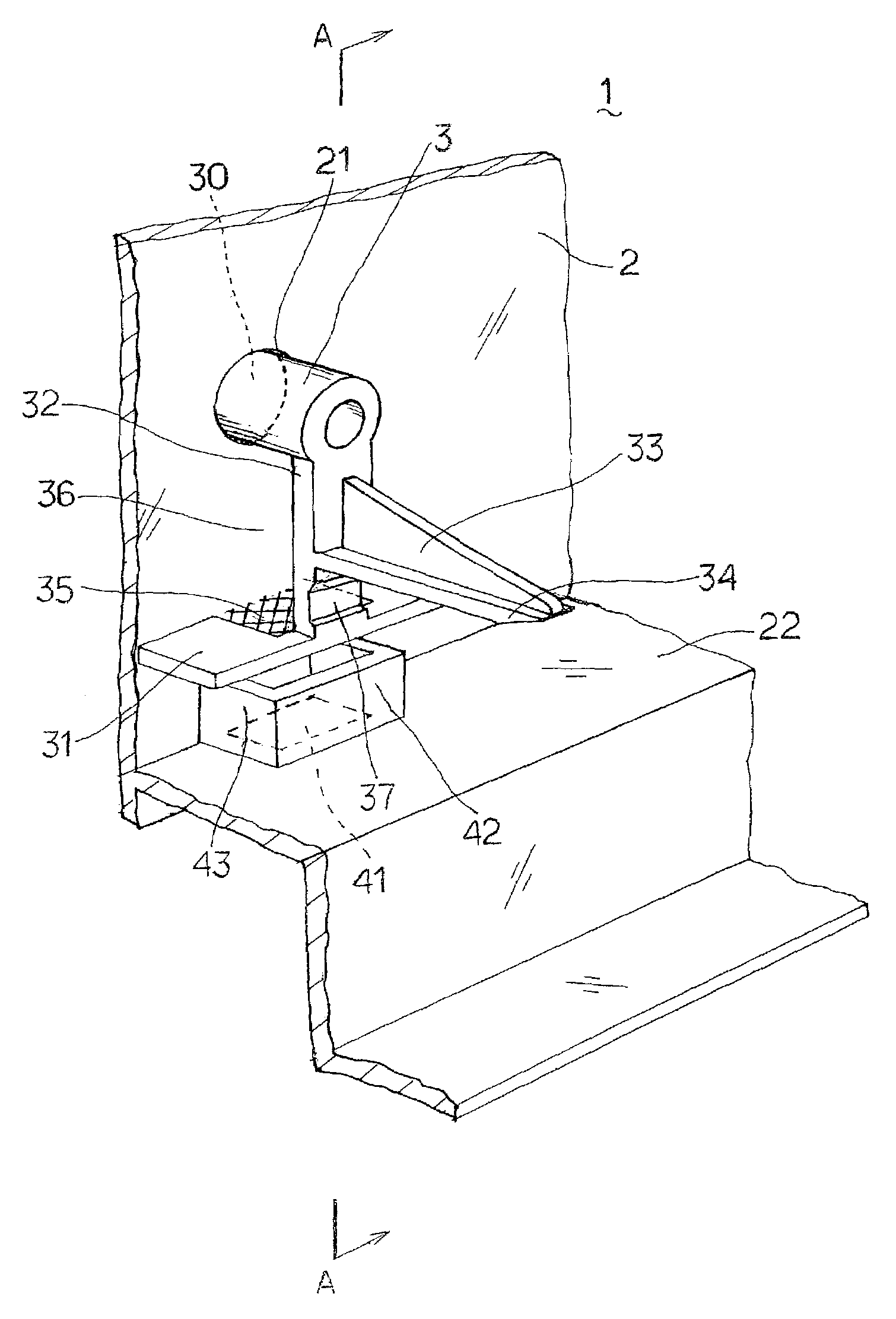
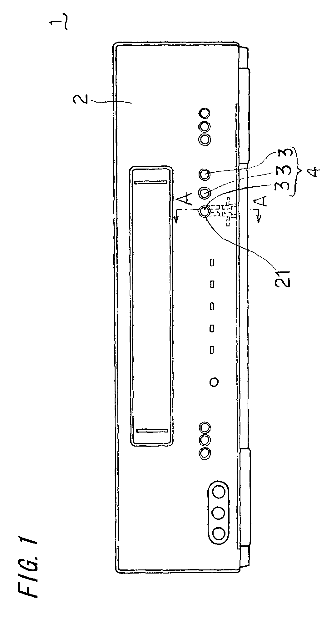
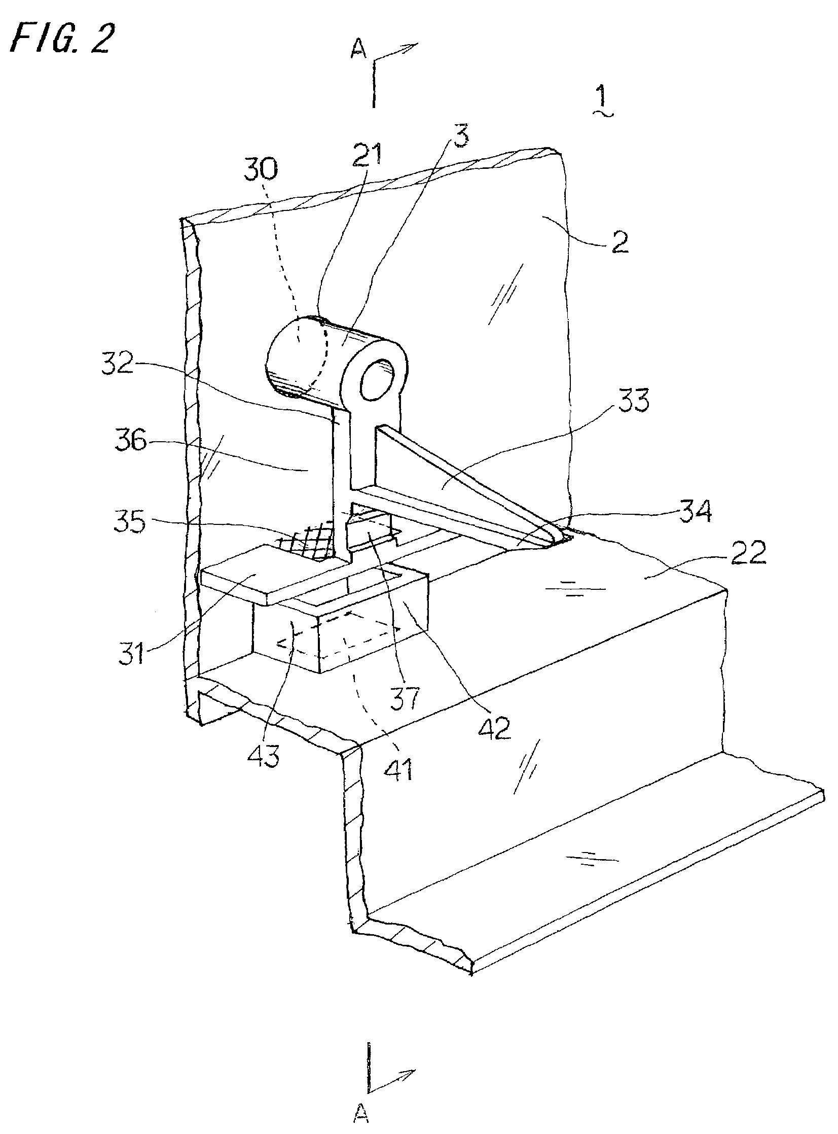
[0020]Now, a front panel for a video cassette recorder according to one embodiment of the present invention will be described, referring to the accompanying drawings. FIG. 1 shows a front view of the front panel, FIG. 2 shows the structure of a push button disposed at the back of the front panel, and FIG. 3 shows the front panel taken along section lines A—A. The front panel 1 is made of resin and installed in the front of a video cassette recorder. The front panel 1 includes a face plate 2 serving as the front surface of the video cassette recorder and a set of buttons 4 composed of a plurality of push buttons 3 for inputting a variety of operation commands from a user to the video cassette recorder. As shown in FIG. 4, the face plate 2 and the set of buttons 4 are formed integrally to each other by injection molding with a mold including a cavity part 7, a core part 8, and a slidable core 9. As can be seen from FIG. 1, push buttons 3 in each button set 4 are arranged in a row at a...


PUM

PropertyMeasurementUnit
angleaaaaaaaaaa
areaaaaaaaaaaa
elasticaaaaaaaaaa

Abstract

A front panel for electrical equipment is provided that has a plurality of push buttons formed integrally with the front panel and requires no additional panel for covering around the push buttons while being excellent in appearance. Each of the push buttons is linked to the face plate of the front panel through a button supporting portion and a button arm. The button supporting portion is extended from the back of the face plate at a substantially right angle to the face plate. The button arm is extended from the rear end of the button supporting portion so as to be parallel to the face plate. The face plate and the button arm are arranged, with a space formed by removing a slidable core, to overlap each other when viewed from front. Thus, the front panel does not require any additional cover panel.

Description

BACKGROUND OF THE INVENTION[0001]The present invention relates to front panels to be installed in the front of electrical equipment such as video cassette recorders or the like.[0002]Conventionally, the push buttons of a front panel for electrical equipment are formed separately from the main panel. In the subsequent assembling of the front panel, the push buttons are fitted to the main panel and joined to the main panel by welding for example. However, the front panel to be constructed in such a manner requires increased components as well as increased steps in assembling, thus hardly reducing the manufacturing cost of the front panel. Therefore, a front panel has been proposed that has push buttons formed integrally with the main panel.[0003]FIG. 7 shows a cross section of the front part of a video cassette recorder having such a front panel. A front panel 100 includes a main panel 102 for covering the front of electrical equipment, push buttons 103 for entering a variety of comma...

Claims


Application Information

Patent Timeline
Patent Type & Authority Patents(United States)
IPC IPC(8): H01H13/04H01H13/08G11B15/10G11B19/02H04N5/64
CPCG11B15/106G11B19/022H04N5/64
Inventor MORISADA, KATSUHIRO
Owner FUNAI ELECTRIC CO LTD
Learn More