
Color filter substrate with plurality of spacers having predetermined relative positions for selected ones of color filters and display device

Active Publication Date: 2006-09-05
SHARP KK
View PDF4 Cites 4 Cited by
  • Summary
  • Abstract
  • Description
  • Claims
  • Application Information

AI Technical Summary

Benefits of technology

[0017]In order to overcome the problems described above, preferred embodiments of the present invention provide a display device which can present an image at a high resolution and with an excellent color balance maintained, and also provide a color filter substrate which can be used effectively in such a display device.

Problems solved by technology

However, as the display quality of LCDs has been further improved, the inevitable decrease in the display quality due to the presence of those spacers has become more and more significant.
For that reason, it is difficult to distribute the spacers at sufficiently uniform densities over the entire display screen, thus possibly making the cell gap non-uniform or causing some display defects due to the agglomeration of the spacers.
However, the present inventors discovered via experiments that the following problems arise when those columnar spacers are used.
Also, once the relative positions of the two substrates have deviated, deterioration in display quality (e.g., decrease in aperture ratio) will be caused.
As a result, the cell gap may also become non-uniform.
Furthermore, if the width of the black matrix (i.e., the width of the gaps between adjacent picture elements) is minimized to maximize the aperture ratio in a high-definition LCD, then even slight misalignment will affect the display quality seriously.
That is to say, once the orientation directions of liquid crystal molecules are disturbed by the columnar spacers on the black matrix, the liquid crystal molecules are also misaligned inside of the picture elements, thus deteriorating the display quality significantly.
As a result, the display quality locally decreases significantly.

Method used


Image

  • Color filter substrate with plurality of spacers having predetermined relative positions for selected ones of color filters and display device
  • Color filter substrate with plurality of spacers having predetermined relative positions for selected ones of color filters and display device
  • Color filter substrate with plurality of spacers having predetermined relative positions for selected ones of color filters and display device

Examples


Embodiment Construction

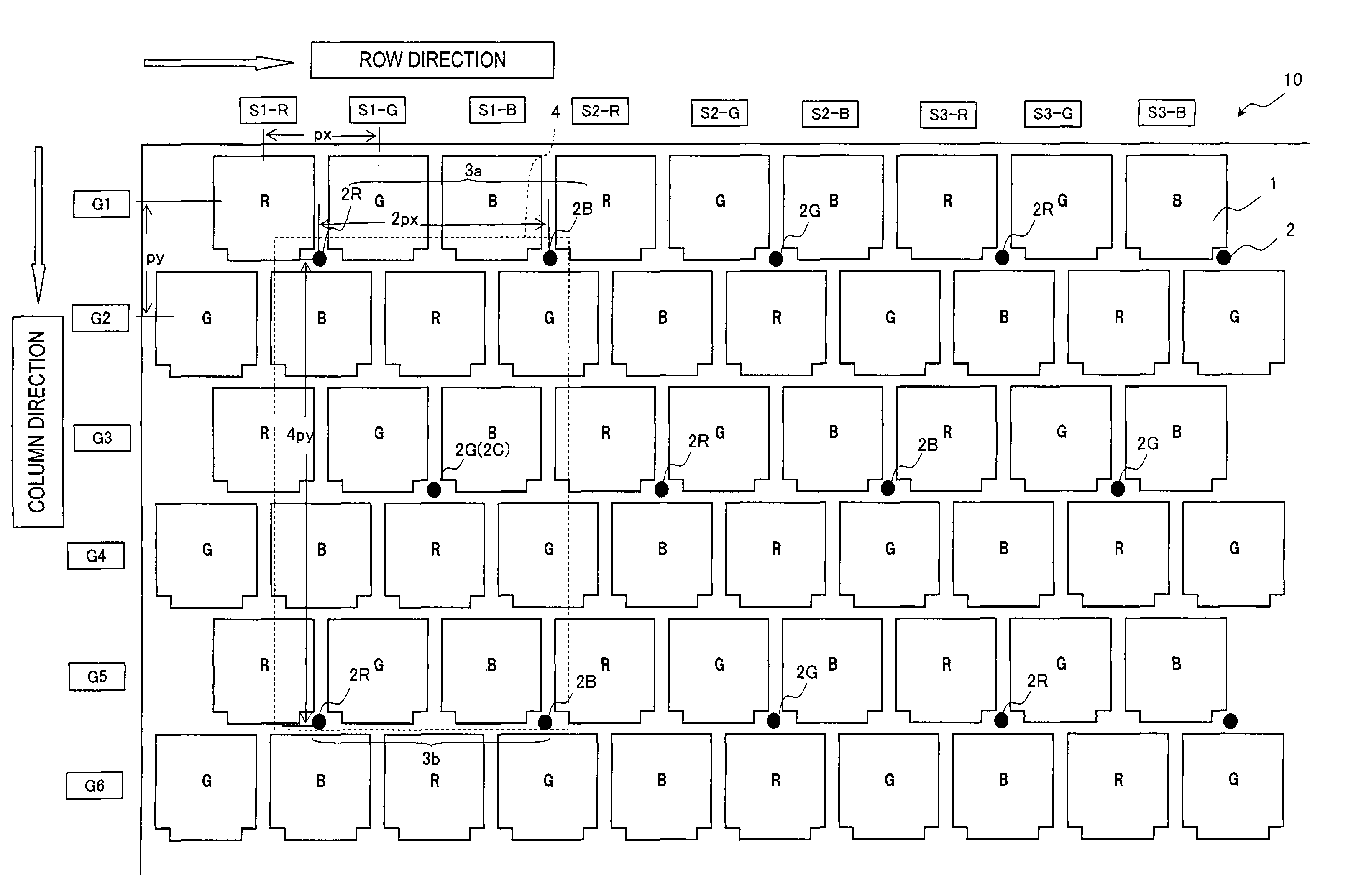
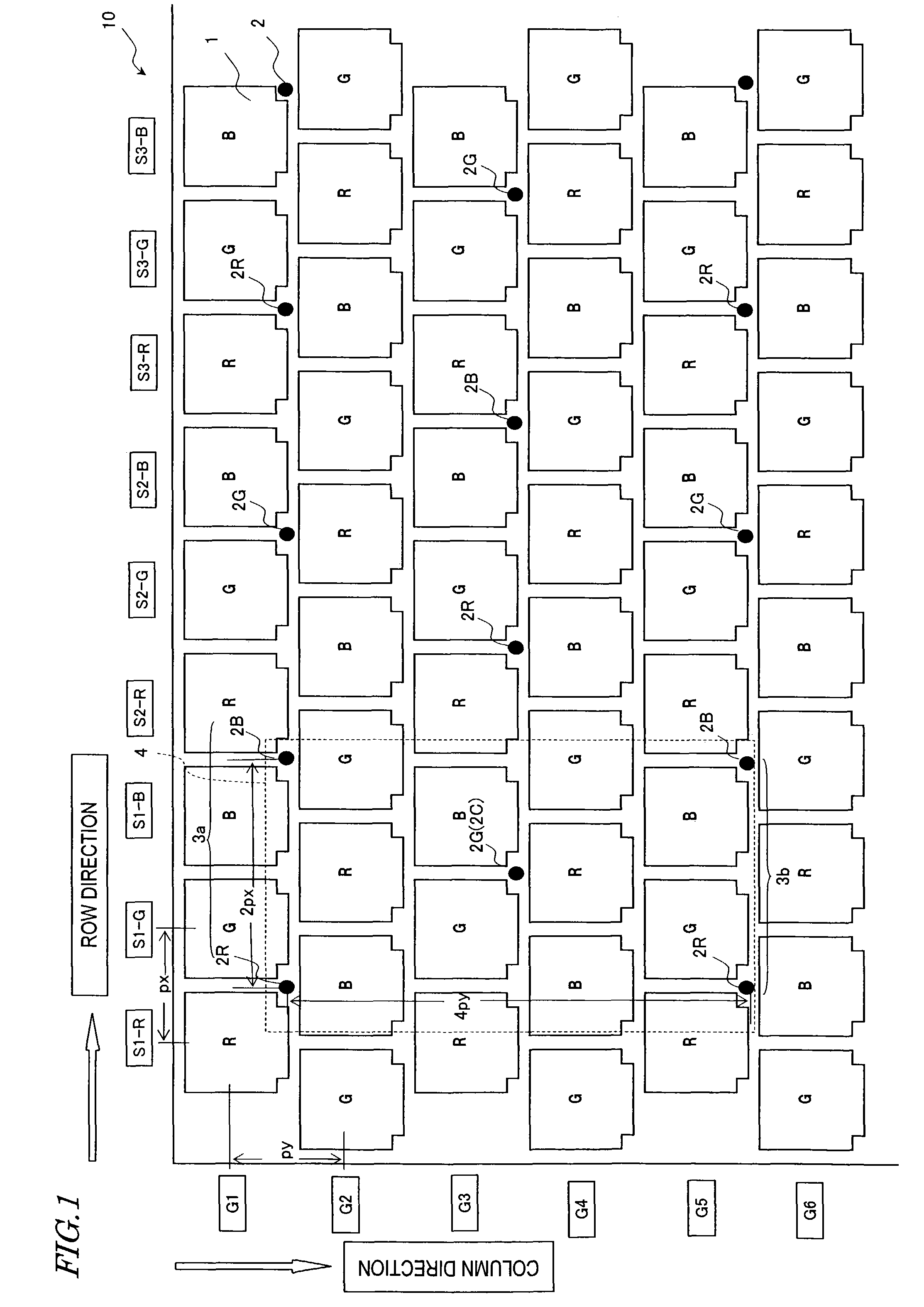
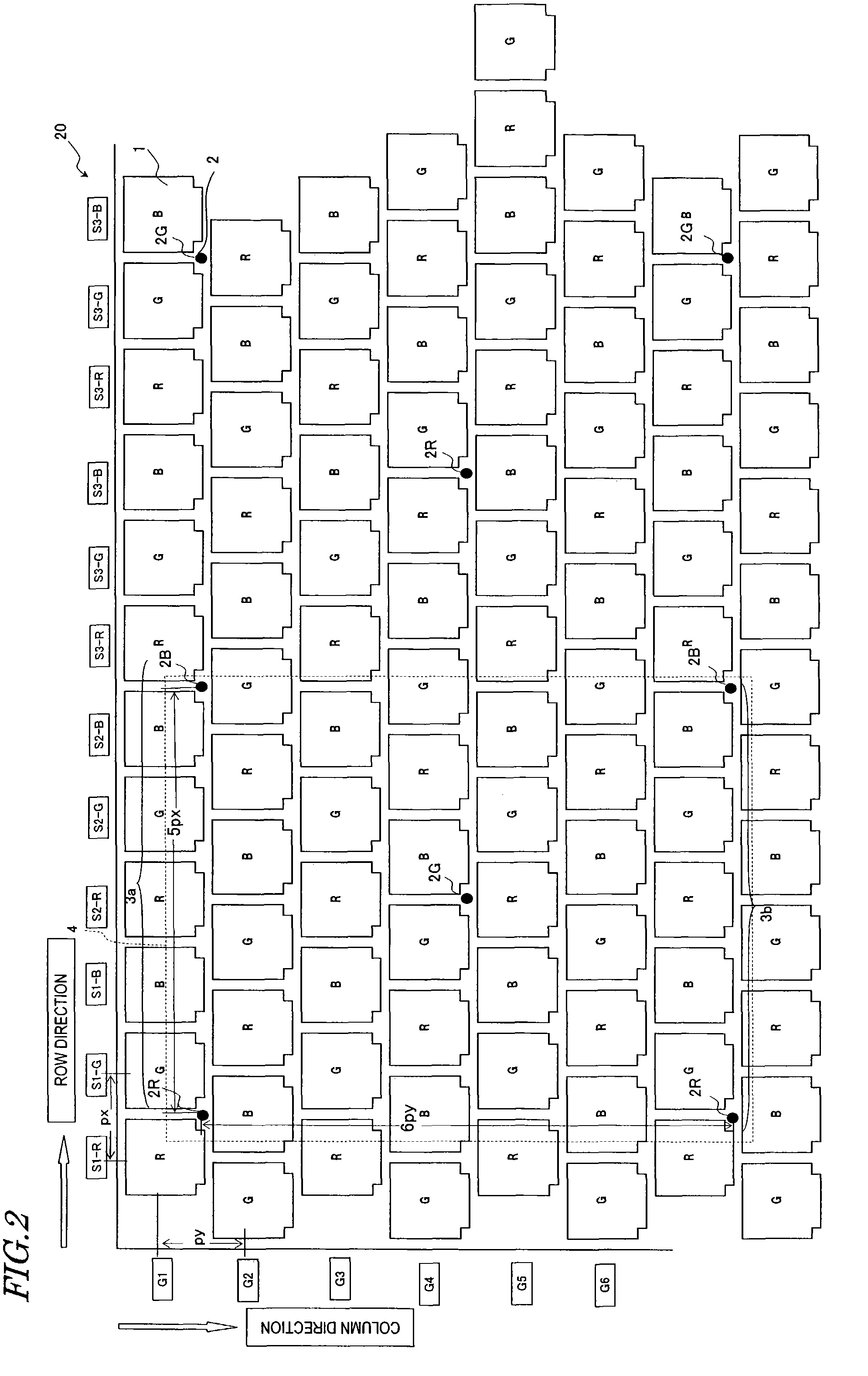
[0049]Hereinafter, exemplary arrangements of columnar spacers in a display device and a color filter substrate according to various preferred embodiments of the present invention will be described with reference to FIGS. 1 through 6. As in the background section, preferred embodiments of the present invention will be described as being applied to a TFT LCD. However, the present invention is in no way limited to the following specific preferred embodiments. Also, in FIGS. 1 through 6, each component having substantially the same function as the counterpart of the conventional arrangement shown in FIG. 7 or 8 will be identified by the same reference numeral and the description thereof will be omitted herein. FIGS. 1 through 6 are plan views schematically showing arrangements for TFT LCDs according to various preferred embodiments of the present invention. The arrangement shown in each of these drawings is an arbitrary portion of a display panel.

[0050]In the LCD 10 shown in FIG. 1, the...


PUM


Abstract

A color filter substrate includes a base member, a color filter layer, and spacers. The color filter layer is provided on the base member and made up of first, second and third groups of color filters, which transmit light rays representing three different colors, respectively. The spacers are provided at predetermined relative positions for selected ones of the color filters. The selected color filters consist of color filters belonging to the first group, color filters belonging to the second group, and color filters belonging to the third group. The spacers are arranged such that in the selected color filters, the smallest number of color filters of the first, second or third group is at least 80% of the largest number of color filters of the first, second or third group.

Description

BACKGROUND OF THE INVENTION[0001]1. Field of the Invention[0002]The present invention relates to a color filter substrate and a display device. More particularly, the present invention relates to a special positional relationship between color filters and spacers that can be used effectively in a high-definition display device and a color filter substrate.[0003]2. Description of the Related Art[0004]A color liquid crystal display (LCD) currently used extensively is provided with color filters for respective picture elements (also called “dots). Typically, three groups of color filters to transmit light rays representing the three primary colors of red (R), green (G) and blue (B), respectively (which will be referred to herein as “R, G and B color filters”) are arranged in a predetermined pattern for those picture elements. One pixel is made up of three picture elements (dots) provided with the R, G and B color filters (which will be referred to herein as “R, G and B picture elements...

Claims


Application Information

Patent Timeline
IPC IPC(8): G02F1/1335G02F1/1339G02B5/20
CPCG02F1/13394G02F1/133514G02F1/1335
Inventor JOHGAN, SHINGOSHIRAKI, ICHIROHYOSHIDA, KEISUKE
Owner SHARP KK
Learn More