
Method and system for monitoring the use of a resource in a processing system

a technology of processing system and resource, applied in the field of method and system for monitoring the use of resource in the processing system, can solve the problems of most time-consuming and critical tasks for computer system operators and users, unstable computing environment, and severe problems not only in single-user environments, but also in multi-user networking environments

Active Publication Date: 2006-09-05
IBM CORP
View PDF17 Cites 38 Cited by
  • Summary
  • Abstract
  • Description
  • Claims
  • Application Information

AI Technical Summary

Problems solved by technology

When the resources fall below these threshold levels, the computing environment can become unstable.
This can cause severe problems not only in single user environments, but also in multi-user networking environments.
Many of the most time consuming and critical tasks for computer system operators and users result from the need to monitor a set of related resources for excessive use of limited resources and / or setting of allocation of that resource to multiple operations.

Method used


Image

  • Method and system for monitoring the use of a resource in a processing system
  • Method and system for monitoring the use of a resource in a processing system
  • Method and system for monitoring the use of a resource in a processing system

Examples


example

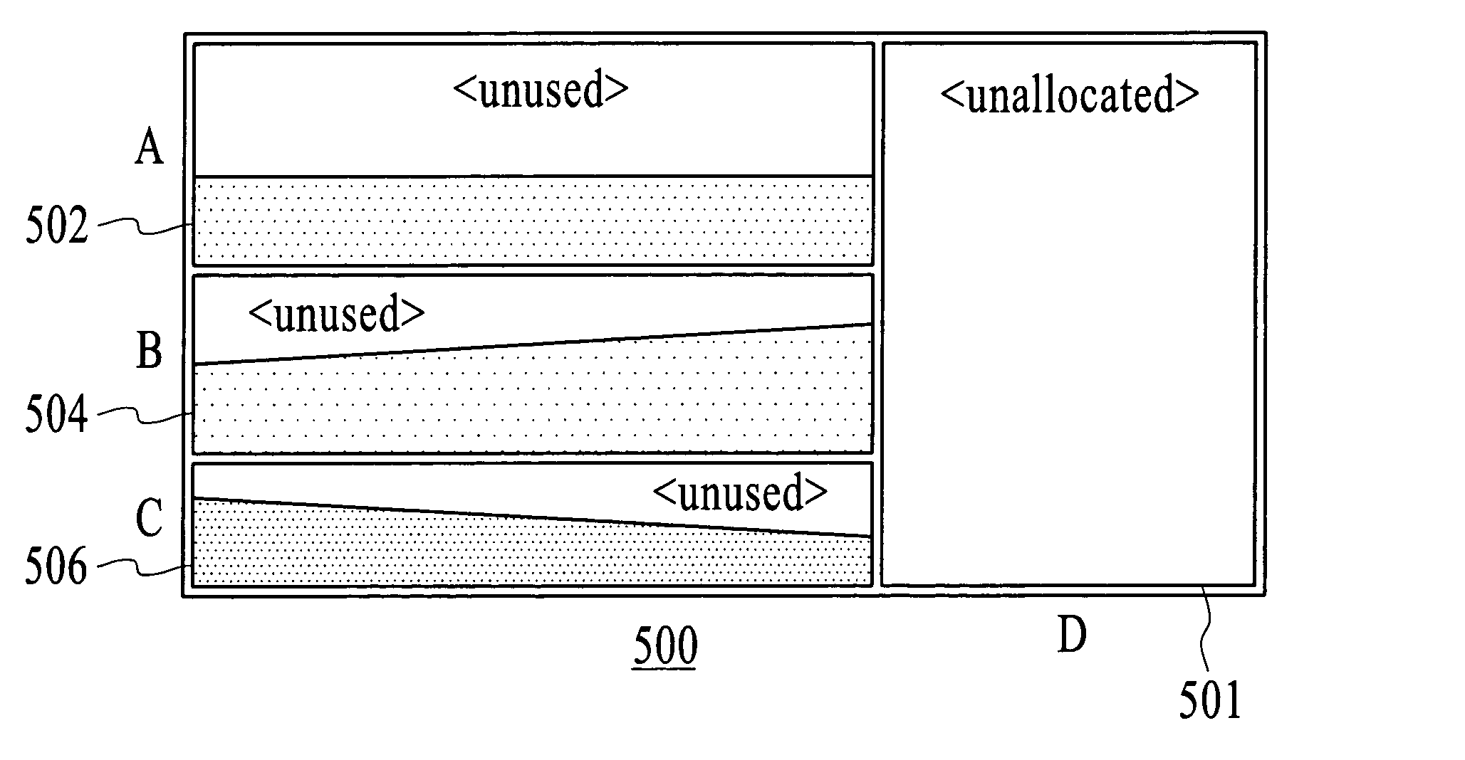
[0038]In this example the available space on a disk (the resource) is monitored as file systems (objects) are allocated to the resource. The following example illustrates the monitoring of available space as the user adds file systems with specific sizes, and the file systems are filled from their initial capacity on the disk. Thereafter, the expansion of the file system will be shown. In addition, some of the specific capabilities in a system and method in accordance with the present invention will be discussed.

Initiate the Display of a Representation of a Total Resource

[0039]First, a total resource graphic will be displayed. This initiation of this display is accomplished by selecting from a predetermined set of choices. A resource is represented by initiation of a general graphics box on a display.

[0040]FIG. 3 illustrates the resource, i.e., the volume group of the disk, as a total resource graphic 250, for example, which has no file systems yet defined because there are no speci...


PUM


Abstract

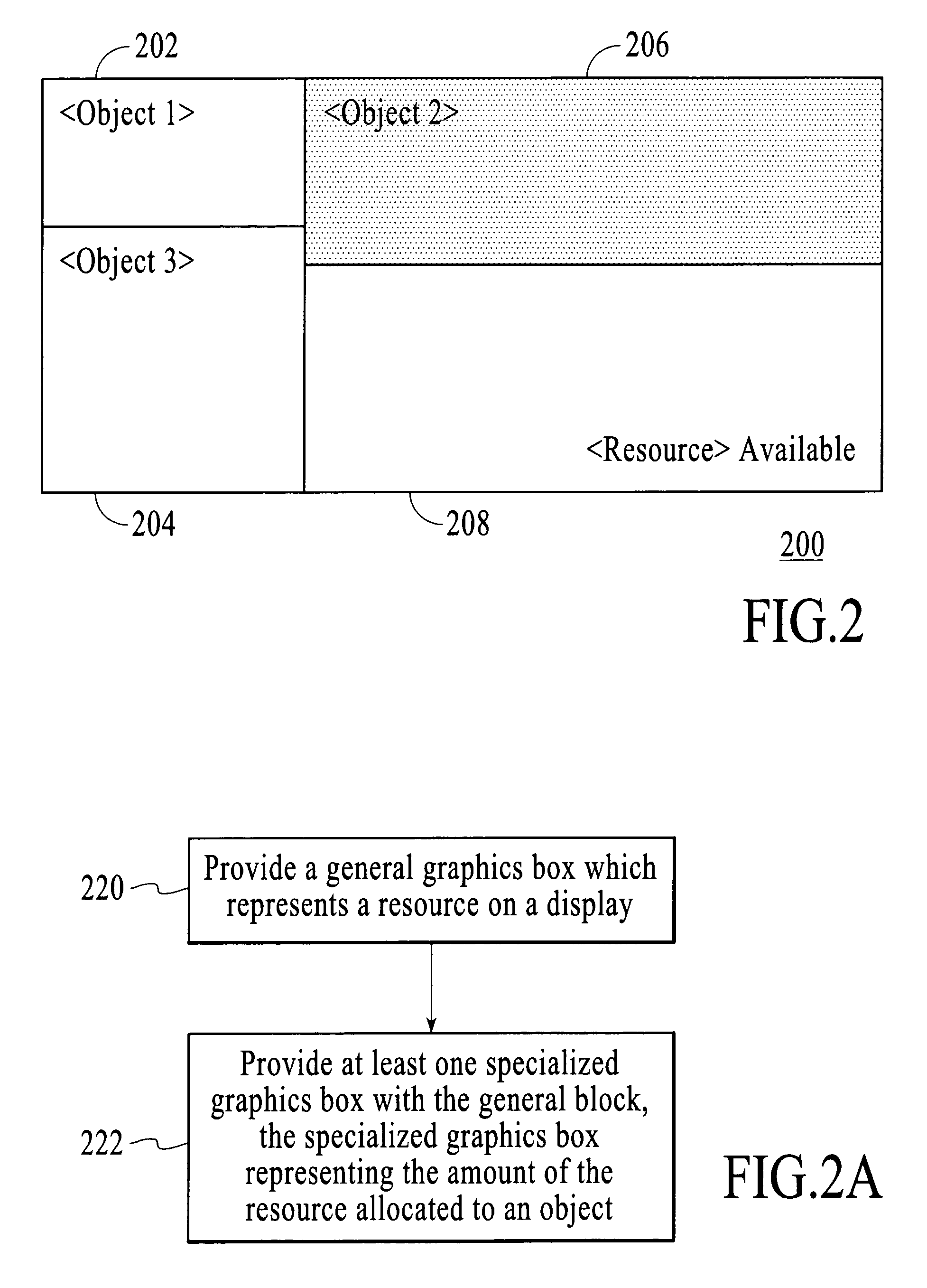
A system for monitoring a resource in a processing system is disclosed. The processing system includes a display. The system comprises a total resource graphic provided on the display. The total resource graphic represents the total resource. The system includes at least one allocation graphic provided within the total resource graphic. The allocation graphic represents the proportion of the resources allocated to an object. The system and method in accordance with the present invention allows for allocation of a resource across all demands, the relative size of the allocations, and the usage of the resource by the individual demanding operation within a single graphical object. In addition, the object would provide for changes to that allocation by direct manipulation, in addition, the status indicator would provide additional information on demand by the user. The graphical object will provide a single view of the total resource available, the allocation of that resource to individual operations, and the amount of the allocated resource to each operation currently in use. Therefore, in a preferred embodiment, a computer is used to perform the numeric calculations of the allocations and provides a single picture to the user. The user can then derive information regarding the relative importance of any single element. This enables the computer and the user or users to perform the functions for which they are best suited within the operation (computers are best suited to perform calculations; humans users of computers are bested suited to seek patterns and assign relevance to their needs).

Description

FIELD OF THE INVENTION[0001]The present invention relates in general to a configurable device for tracking and monitoring dynamic properties of resources and events coupled to a computing environment.BACKGROUND OF THE INVENTION[0002]Computers are a regular part of the everyday life of many people. Computers are typically used in one's home as well as one's business or work place. A computer monitor is one of the main interfaces used to enable a person to interact with the computer. The computer monitor has a display screen for displaying information, usually in graphic format, to the user. Input devices, such as a mouse and a keyboard, are also devices that are used to interface a user with the computer.[0003]The junction between a user and a computer is commonly referred to as a user interface. A user interface is typically in the form of a set of commands and menus through which a user communicates with the computer. A command-driven interface is one in which a user enters command...

Claims


Application Information

Patent Timeline
IPC IPC(8): G06F3/00G09G5/00
CPCG06F11/3466Y10S715/966
Inventor ALFORD, JR., JACK ALLENBANNING, KENNETH RAYLENTZ, JAMES LEE
Owner IBM CORP
Learn More