
Anchor bolt and setting template

a technology of anchor bolts and templates, applied in the field of anchor bolts and anchor bolts setting templates, can solve the problems of difficulty in positioning anchor bolts, higher cost, and higher material and labor costs of anchor bolts that are set into cured concr

Inactive Publication Date: 2006-09-12
KASTBERG DAVID J
View PDF28 Cites 29 Cited by
  • Summary
  • Abstract
  • Description
  • Claims
  • Application Information

AI Technical Summary

Benefits of technology

"The present invention is a template for setting anchor bolts in walls to attach plates to the wall. The template is made of plastic and can be thin and easily left in place after use. The template has indicia for use with different plate sizes and includes projections to secure the bolt to the plate. The template can also have a removable sleeve that overlies the opening and has stop means to prevent over-insertion of the anchor bolt. The invention provides a simple and efficient way to set anchor bolts in walls for attachment of plates."

Problems solved by technology

Anchor bolts that are set into cured concrete are typically more costly both in material and labor than those that are set into “wet” concrete.
The higher cost is due to the more complex nature of the bolt (e.g., split bolt sleeves) and the costs incurred in drilling a hole into the cured and set concrete.
On the other hand, while bolts that are set into “wet” concrete are easier to install and less costly, there are difficulties with positioning these bolts.
While such a device may function well, it is impractical in that it must be threaded onto the bolt and the entirety of the device removed from the bolt in order to make use of the bolt.

Method used


Image

  • Anchor bolt and setting template
  • Anchor bolt and setting template
  • Anchor bolt and setting template

Examples


Embodiment Construction

[0023]While the present invention is susceptible of embodiment in various forms, there is shown in the drawings and will hereinafter be described a presently preferred embodiment with the understanding that the present disclosure is to be considered an exemplification of the invention and is not intended to limit the invention to the specific embodiment illustrated.

[0024]It should be further understood that the title of this section of this specification, namely, “Detailed Description Of The Invention”, relates to a requirement of the United States Patent Office, and does not imply, nor should be inferred to limit the subject matter disclosed herein.

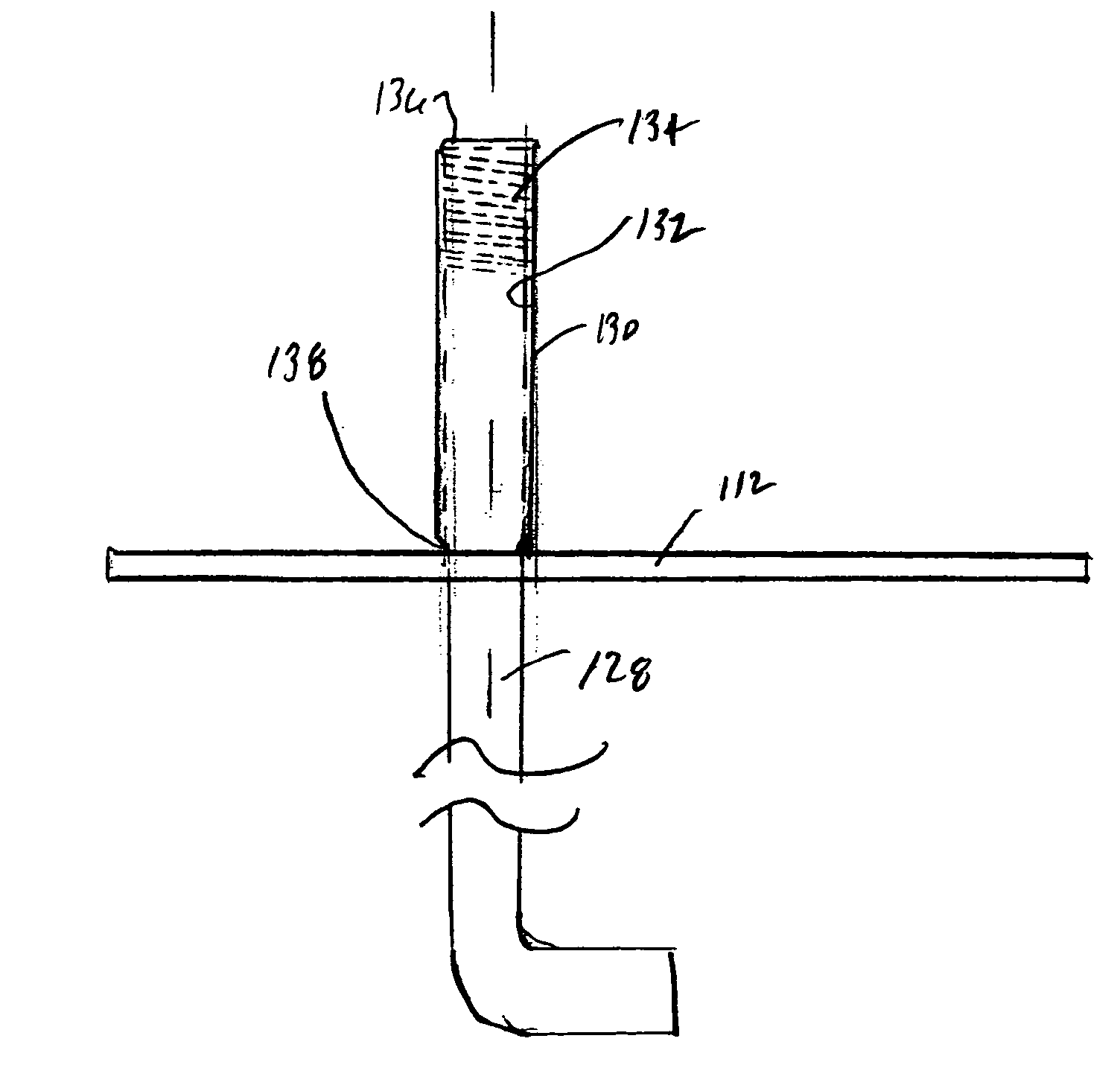
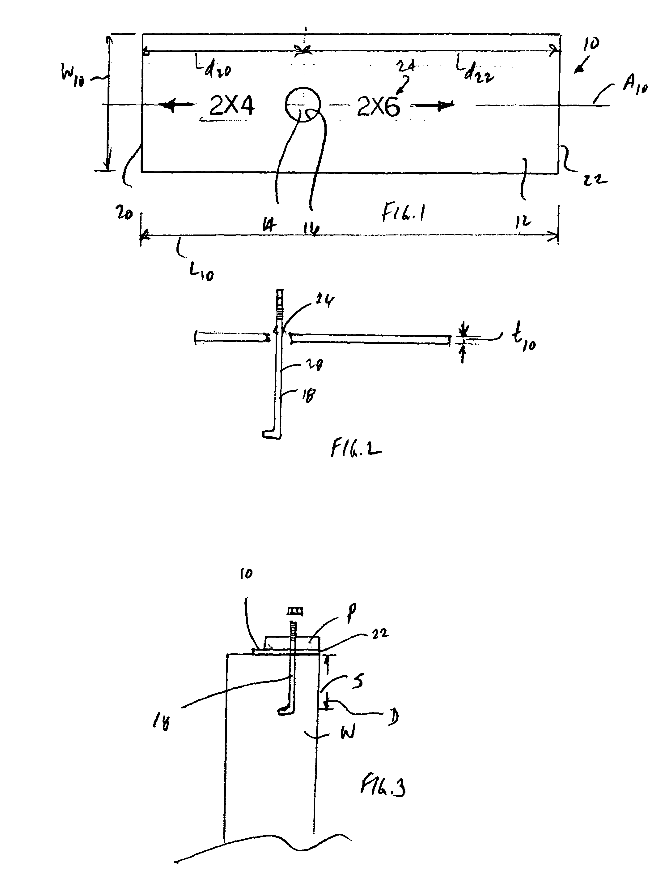
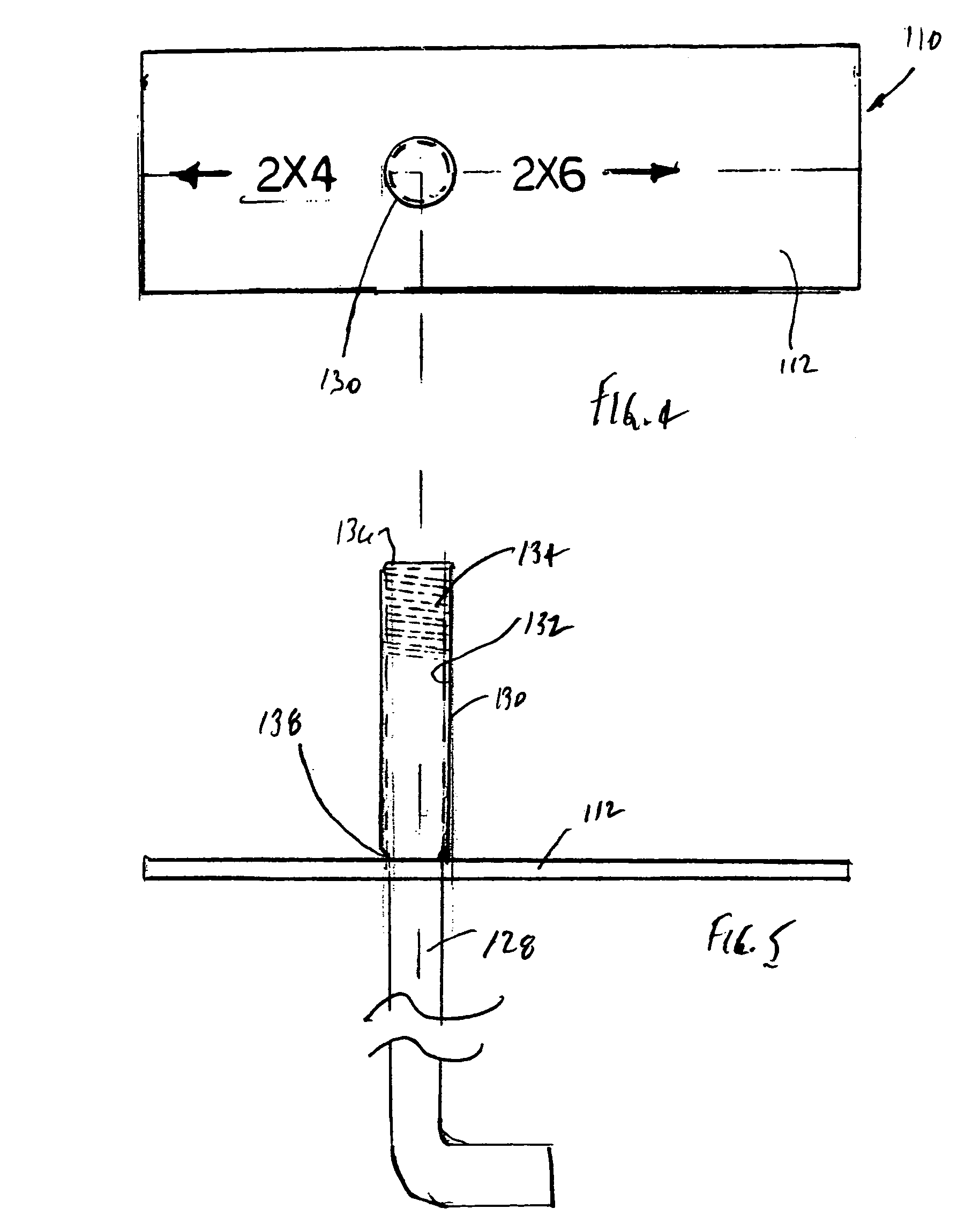
[0025]Referring now to the drawings in particular to FIG. 1 there is shown an anchor bolt setting template 10 embodying the principles of the present invention. The template 10 is formed as a dimensioned rigid washer plate 12 having an opening 14 formed therein. The opening 14 is defined by an opening edge 16. Preferably, the opening 14 ...


PUM


Abstract

An anchor bolt setting template is used to position an anchor bolt in a wall for attachment of a first plate or a second plate to the wall. The first and second plates having different dimensions from each other. The template includes a rigid washer plate having first and second ends and defining a longitudinal axis extending between the first and second ends. An opening is formed in the washer plate lying along the longitudinal axis. The opening is non-equidistant between the first and second ends and defines a first distance between the opening and the first end and a second distance between the opening and the second end. The first distance is established to position the anchor bolt in the wall to properly position the first plate for attachment to the wall, and the second distance is established to position the anchor bolt in the wall to properly position the second plate for attachment to the wall. The template can include a sleeve frangibly connected to the plate for receiving the bolt. The template in combination with an anchor bolt is also disclosed.

Description

BACKGROUND OF THE INVENTION[0001]The present invention relates to an anchor bolt and bolt setting template. More specifically, the present invention relates to a template for an anchor bolt for setting the distance and depth of the bolt and a bolt for use therewith.[0002]Anchor bolts are used in all manner of construction projects, commercial as well as residential. Anchor bolts are used to secure a structural element or member to concrete. Anchor bolts are of two types, namely those installed in concrete that has already cured (drilled and installed in a drilled hole) and those that are set into concrete while the concrete is still “wet”.[0003]Anchor bolts that are set into cured concrete are typically more costly both in material and labor than those that are set into “wet” concrete. The higher cost is due to the more complex nature of the bolt (e.g., split bolt sleeves) and the costs incurred in drilling a hole into the cured and set concrete. On the other hand, while bolts that ...

Claims


Application Information

Patent Timeline
Patent Type & Authority Patents(United States)
IPC IPC(8): E02D27/00E04B1/41E04G21/18G01B3/14
CPCE04G21/185E04B1/4157
Inventor KASTBERG, DAVID J.
Owner KASTBERG DAVID J
Learn More