Method and apparatus for facilitating more uniform vapor distribution in mass transfer and heat exchange columns

a mass transfer and heat exchange column technology, applied in the field of mass transfer and heat exchange columns, can solve the problems of reducing efficiency and undesirable high velocity zones, and achieve the effects of facilitating a more uniform horizontal distribution of vapor, reducing ascending vapor velocity, and improving horizontal vapor distribution

Active Publication Date: 2006-09-12
KOCH GLITSCH INC
View PDF7 Cites 22 Cited by
  • Summary
  • Abstract
  • Description
  • Claims
  • Application Information

AI Technical Summary

Benefits of technology

[0028]From the foregoing, it will be seen that this invention is one well adapted to attain all the ends and objectives hereinabove set forth together with other advantages that are inherent to the structure.

Problems solved by technology

This high velocity zone is undesirable because the high velocity and horizontal maldistribution of vapor reduces the efficiency of the mass transfer or other processing occurring in the overlying zones.

Method used


Image

  • Method and apparatus for facilitating more uniform vapor distribution in mass transfer and heat exchange columns
  • Method and apparatus for facilitating more uniform vapor distribution in mass transfer and heat exchange columns
  • Method and apparatus for facilitating more uniform vapor distribution in mass transfer and heat exchange columns

Examples


Embodiment Construction

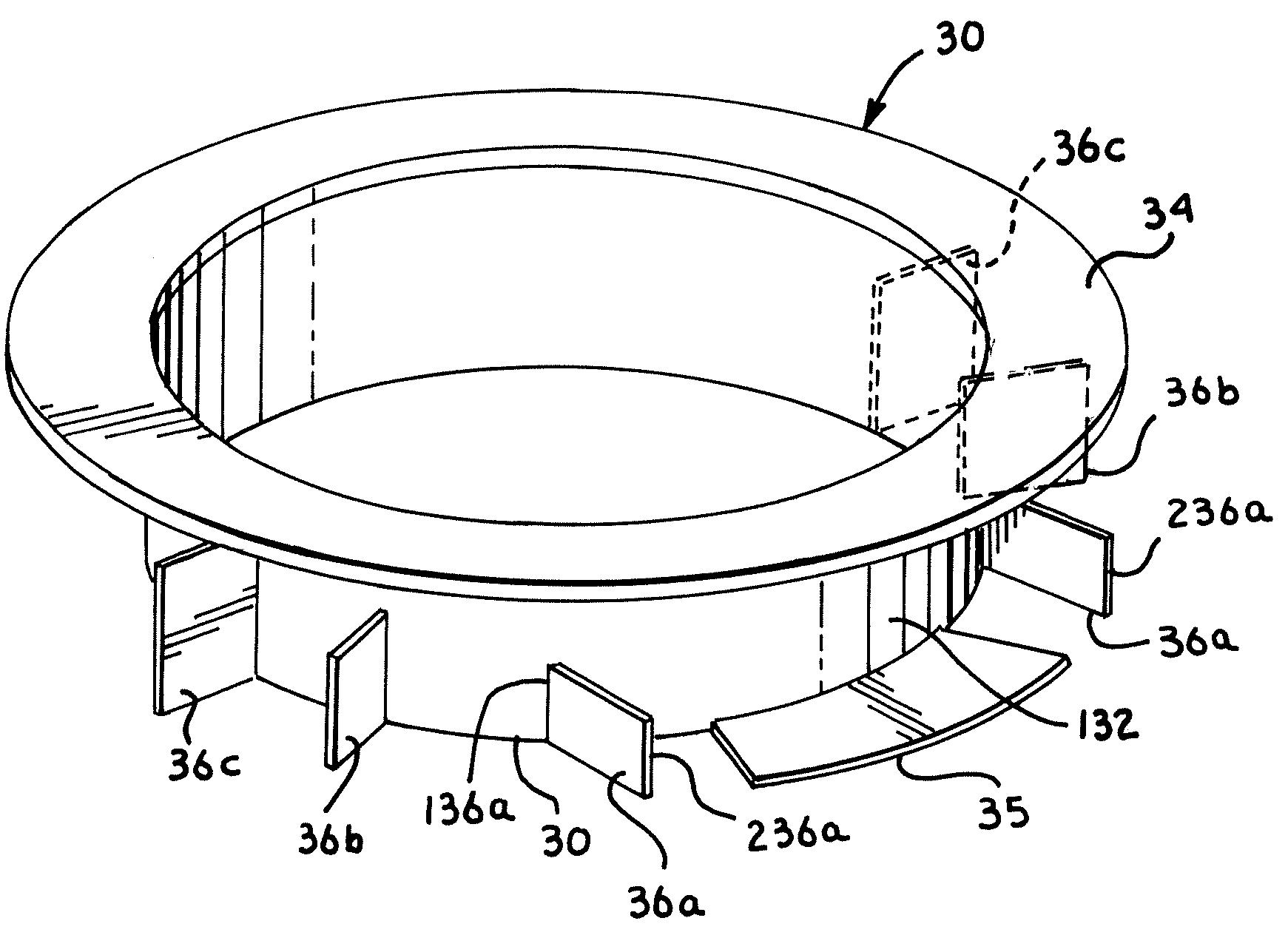
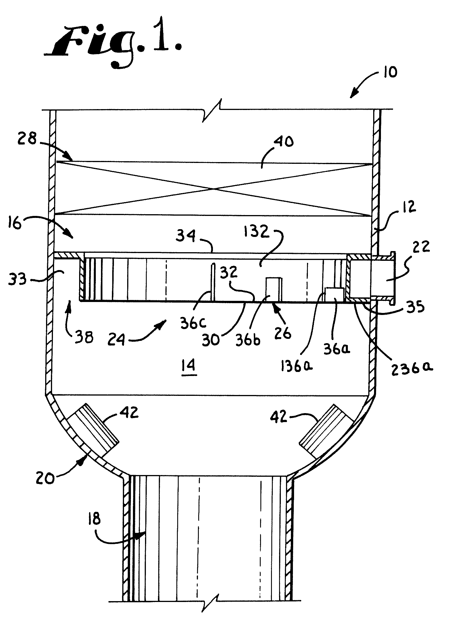
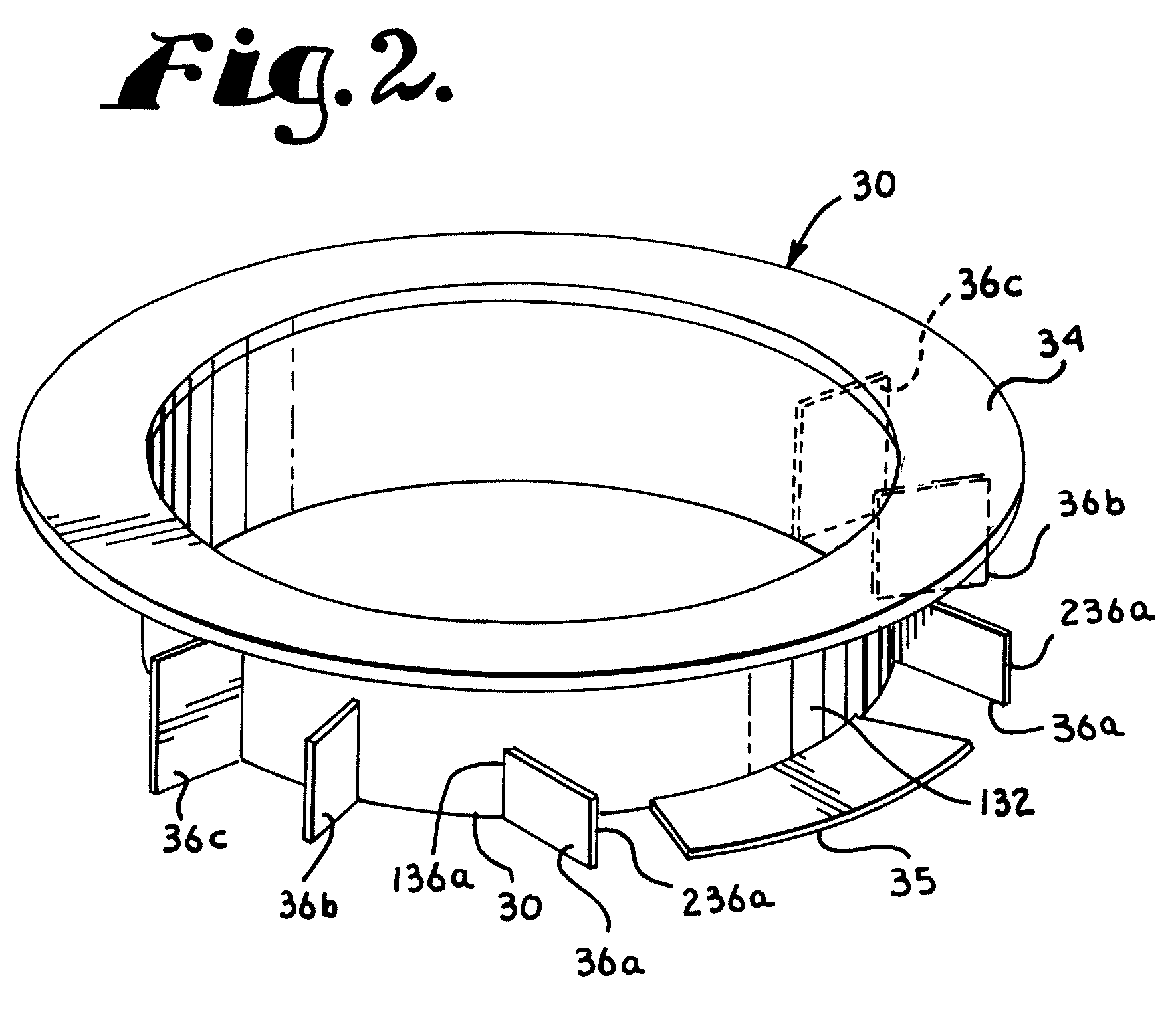
[0016]Referring now to the drawings in greater detail, and initially to FIGS. 1 and 2, a mass transfer or heat exchange column is designated generally by the numeral 10. Column 10 comprises an external shell 12 which defines an open internal region 14 and which has an upper region 16 of a preselected diameter, a lower region 18 of lesser diameter, and a transition region 20 positioned between the upper region 16 and lower region 18. The transition region 20 tapers from the diameter of the upper region 16 at the top to the diameter of the lower region 18 at the bottom. The primary function of the transition region 20 is to provide a transition between the larger diameter of the upper region 16 and the reduced diameter of the lower region 18. To achieve this function, the transition region 20 preferably is an elliptical head as illustrated in FIG. 1, or it may have planar or multi-segmented sides to form other shapes such as hemispherical or conical. An elliptical head having a 2:1 ra...


PUM

PropertyMeasurementUnit
tangential angleaaaaaaaaaa
tangential anglesaaaaaaaaaa

Abstract

A vapor horn device for use in an elongated, generally upright mass transfer and / or heat exchange column having an internal region comprises an elongated, generally arcuate wall arranged to be located within the internal region and disposed to extend around a longitudinal axis of the column. The arcuate wall includes an inlet area positioned for being contacted by a vapor or mixed phase stream entering the column and causing the stream to flow along an outer surface of the arcuate wall and generally around the axis. The device also includes a primary elongated vane extending outwardly from the outer surface of the arcuate wall. This primary vane has an inner end located adjacent the outer surface of the inner wall and an outer end disposed in spaced relationship relative to the outer surface of the wall. The vane is disposed at a tangential angle relative to the direction of flow of the stream such that the inner end of the vane is further downstream than the outer end thereof whereby any portion of the stream impinging on the primary vane is redirected toward the outer surface of the arcuate wall. The device also desirably includes one or more vanes that extend radially outwardly from the inner wall.

Description

CROSS-REFERENCE TO RELATED APPLICATION[0001]Priority benefits under 35 U.S.C. §119(e) are claimed in this application from provisional application Ser. No. 60 / 520,635, filed on Nov. 17, 2003, the entirety of the disclosure of which is hereby specifically incorporated herein by this reference thereto.BACKGROUND OF THE INVENTION[0002]This invention relates in general to mass transfer and heat exchange columns and, more particularly, to methods and apparatus to improve vapor distribution in such columns.[0003]In mass transfer and heat exchange columns, liquid and vapor streams are brought into contact with each other, normally in countercurrent flow, for mass or heat transfer, fractionation or other operations. Various types of internals, such as trays and random and structured packing, have been developed to facilitate interaction between the liquid and vapor streams within selected contact regions of the column. In order to increase the efficiency of the mass transfer or heat exchang...

Claims


Application Information

Patent Timeline
Patent Type & Authority Patents(United States)
IPC IPC(8): B01F3/04B01DB01D3/00B05B7/10
CPCB01D3/008B01D1/00B05B7/02B05B7/10B01F23/20
Inventor LAIRD, DANA G.HAJILOO, AZARDOKHTSCHMUDE, DENNIS
Owner KOCH GLITSCH INC
Why Eureka
Try Eureka