Instrument with illuminated control knob

a technology of control knobs and knobs, applied in the direction of instruments, mechanical control devices, controlling members, etc., can solve the problems of insufficient space, inability to illuminate, and clutter on the front panel

Inactive Publication Date: 2006-09-12
TEKTRONIX INC
View PDF13 Cites 25 Cited by
  • Summary
  • Abstract
  • Description
  • Claims
  • Application Information

AI Technical Summary

Problems solved by technology

However, with the increasing number of functions, the front panel may appear cluttered, may have inadequate space, or there may be confusion as to which label applies to which knob.
However, for sophisticated applications requiring controls meeting demanding electronic specifications, such illumination is impractical because such controls are not designed to transmit the needed light.
Illumination techniques for such controls would generally lead to an unattractive or non-uniform result.
While a custom rotary switch having certain optical properties or configuration may be designed, this is often impractical for many applications where only small quantities are required (unlike the automotive industry) and where there is cost sensitivity (unlike the aerospace industry.)

Method used


Image

  • Instrument with illuminated control knob
  • Instrument with illuminated control knob
  • Instrument with illuminated control knob

Examples


Embodiment Construction

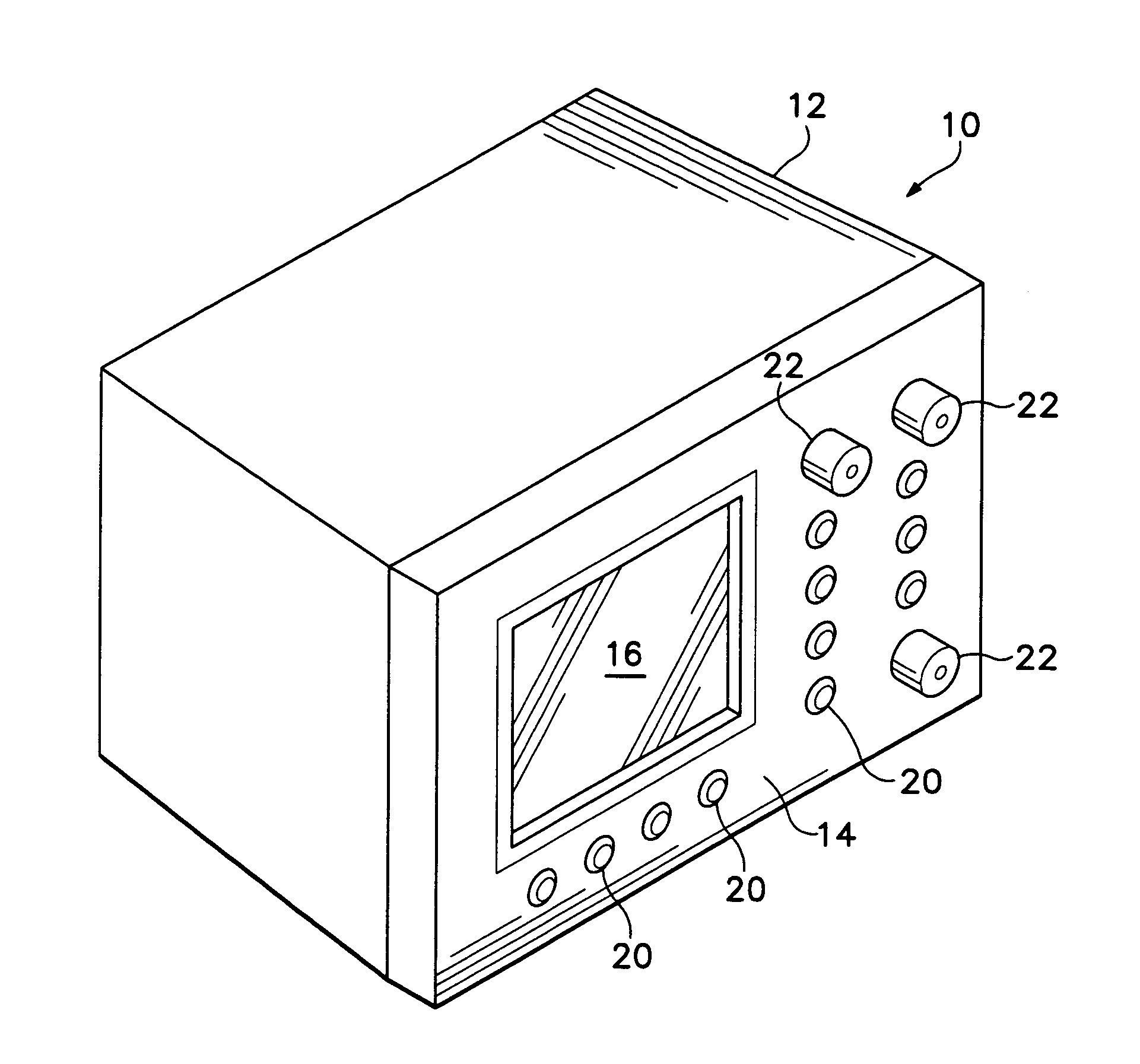
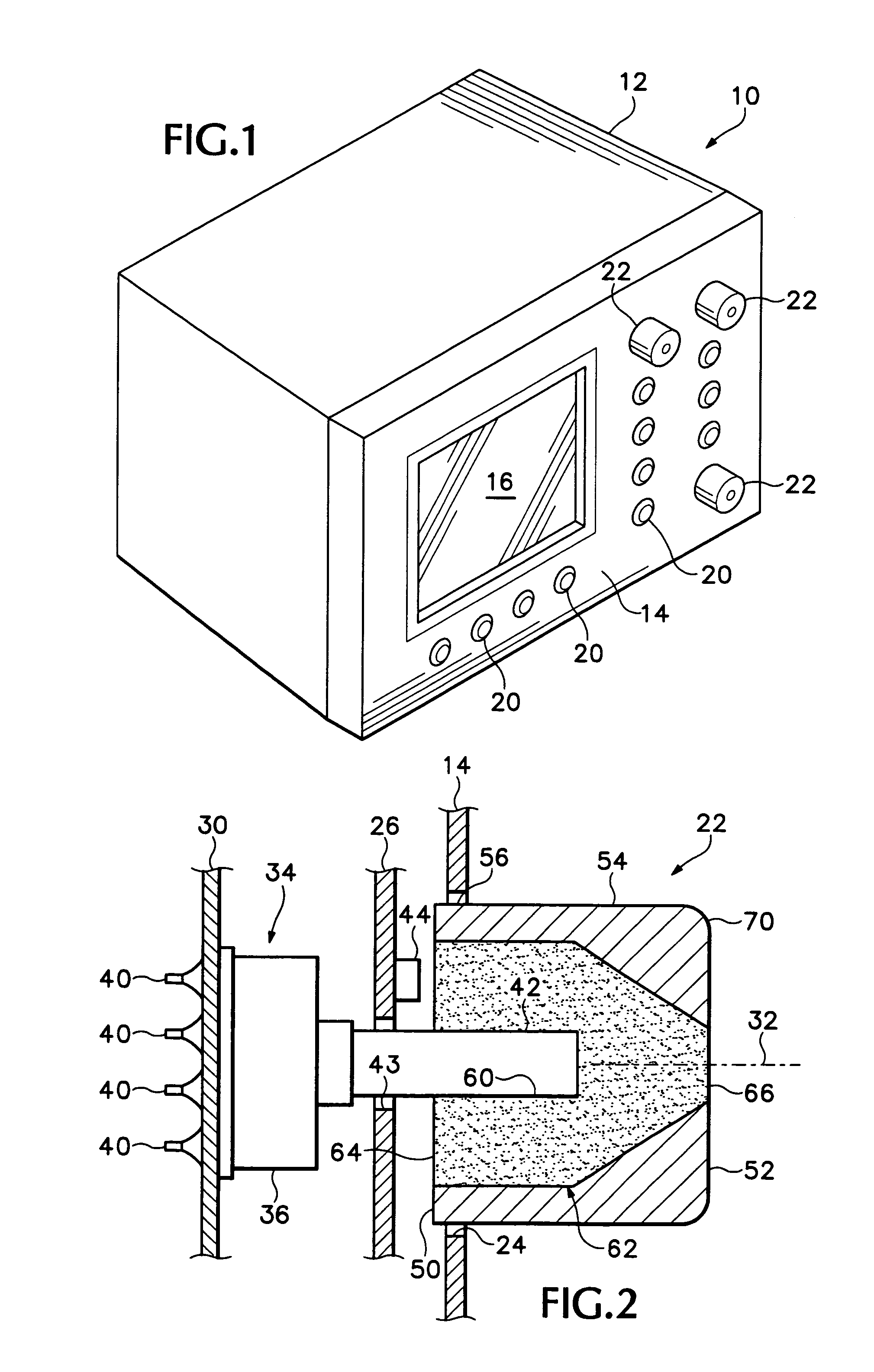
[0013]FIG. 1 shows an electronic instrument 10 with a housing 12 containing circuitry (not shown). The housing has a front panel 14 on which are provided a display screen 16, and an array of buttons 20 and rotary knobs 22.

[0014]As shown in FIG. 2, the front panel 14 defines a circular aperture 24 that closely receives the knob 22. A first circuit board 26 resides parallel to and behind the panel 14 in the housing, and a second board 30 resides behind the first board. A knob axis 32 defines a rotational axis of the knob, and the center of the aperture 24. A rotary switch 34 is mounted to the second board 30, with a body 36 against a forward facing surface of the second board, and contacts 40 electrically connected to the board and to other instrument circuitry. The body is a flat circular disc, with a rotating shaft 42 protruding in a forward direction along the axis 32. As is typical for conventional rotary switches, the switch body and shaft are opaque. One example of such a rotary...


PUM


Abstract

An electronic instrument has a rotary switch with an extending shaft, a light source proximate to the shaft, and a knob attached to the shaft. The knob has a body with a rear face, an opposed front face, and side surfaces extending between the faces. The rear face defines a bore sized to receive a free end of the shaft. The body has a light-transmissive portion extending from a first surface portion of the rear face surrounding the bore, such that light from the light source enters the light transmissive portion regardless of the rotary position of the knob. The light-transmissive portion of the body extends to a window in the side surface or the front face.

Description

FIELD OF THE INVENTION[0001]The subject invention generally relates to the field of control switches and knobs for electronic instruments.BACKGROUND OF THE INVENTION[0002]Electronic instruments such as Digital Oscilloscopes and other test and measurement equipment typically have an array of control knobs and buttons for selecting functions and adjusting parameters. Some such instruments have multi-function knobs that perform different functions in different circumstances. This permits the use of larger screen sizes on instruments of a given size, with smaller control panels.[0003]When a knob is to perform multiple functions, it is useful to provide some kind of indication to the user about the current function. This has typically been achieved with adjacent illuminated annunciator labels, such as with light sources behind light-transmissive icons or text in a film on the instrument's front panel. However, with the increasing number of functions, the front panel may appear cluttered,...

Claims


Application Information

Patent Timeline
Patent Type & Authority Patents(United States)
IPC IPC(8): H01H9/18
CPCG05G1/105
Inventor MUCHA, JEFF
Owner TEKTRONIX INC
Why Eureka
Try Eureka