Efficient axial airgap electric machine having a frontiron

a frontiron and airgap technology, applied in the direction of dynamo-electric machines, magnetic circuit rotating parts, magnetic circuit shape/form/construction, etc., can solve the problems of difficult or impossible to directly substitute ordinary steel for conventional motors, unable to meet the requirements of axial or radial airgap machines, and previous attempts to incorporate amorphous materials into conventional radial or axial airgap machines have been largely unsuccessful commercially, etc., to achiev

Inactive Publication Date: 2006-09-12
LIGHT ENGINEERING INC
View PDF11 Cites 24 Cited by
  • Summary
  • Abstract
  • Description
  • Claims
  • Application Information

AI Technical Summary

Benefits of technology

[0013]The present invention provides a dynamoelectric electric machine comprising a rotor assembly, and a stator assembly that includes a frontiron section, a backiron section, and a number of stator tooth sections. The electric device can have any pole count ranging from low to high. Preferably the stator comprises a generally toroidal structure employing laminated layers composed of at least one low core loss material selected from the group consisting of amorphous and nanocrystalline metals and optimized Fe-based alloy. However, other soft magnetic materials may also be used in constructing all or part of the stator assembly. The rotor assembly is supported for rotation about an axis and includes a plurality of poles. The assembly is arranged and disposed for magnetic interaction with the stator assembly. The use of low core loss, advanced soft magnetic materials affords significant flexibility in design, by making possible a wider range of pole counts and commutating frequencies, while also maintaining high operating efficiency, high power density, and a wide range of possible operating speeds.

Problems solved by technology

While it is generally believed that motors and generators having rotors constructed with advanced permanent magnet material and stators having cores made with advanced, low-loss soft materials, such as amorphous metal, have the potential to provide substantially higher efficiencies and power densities compared to conventional radial airgap motors and generators, there has been little success in building such machines of either axial or radial airgap type.
Previous attempts at incorporating amorphous material into conventional radial or axial airgap machines have been largely unsuccessful commercially.
Amorphous metal has unique magnetic and mechanical properties that make it difficult or impossible to directly substitute for ordinary steels in conventionally designed motors.
High speed electric machines are almost always manufactured with low pole counts, lest the magnetic materials in electric machines operating at higher frequencies experience excessive core losses that contribute to inefficient motor design.
It is well known that losses resulting from changing a magnetic field at frequencies greater than about 400 Hz in conventional Si—Fe-based materials causes the material to heat, oftentimes to a point where the device cannot be cooled by any acceptable means.
To date it has proven very difficult to cost effectively provide readily manufacturable electric devices, which take advantage of low-loss materials.
Previous attempts to incorporate low-loss materials into conventional machines generally failed, since the early designs typically relied on merely substituting new soft magnetic materials, such as amorphous metal, for conventional alloys, such as silicon-iron, in machine's magnetic cores.
The resulting electric machines have sometimes provided increased efficiencies with less loss, but they generally suffer from an unacceptable reduction in power output, and significant increases in cost associated with handling and forming the amorphous metal.
As a result, they have not achieved commercial success or market penetration.
However, a further problem arising in electric machines capable of operating at high frequencies and high speeds is heating in the rotor.
Those currents in some cases are high enough to cause significant heating in the rotor.
The heating, in turn, is likely to cause irreversible loss of magnetization and reduced device output.
In extreme cases, the heating may even be severe enough to reduce the lifetime of the rotor magnets or destroy them.

Method used


Image

  • Efficient axial airgap electric machine having a frontiron
  • Efficient axial airgap electric machine having a frontiron
  • Efficient axial airgap electric machine having a frontiron

Examples


examples

[0138]Optimized Frontiron Thickness for 15 kRPM Electric Device

[0139]An analysis of the optimized frontiron thickness is performed for a low pole count, high frequency, 15 k RPM electric device with the following specifications:

[0140]

Slots per Stator  12Poles  8RPM15000Frequency1000HzCore OD248mmAxial Length (active)89mmMagnet Axial Length20.3mmAirgap Length2.0mmOutput Power100kWSupply Voltage, line480Vrms

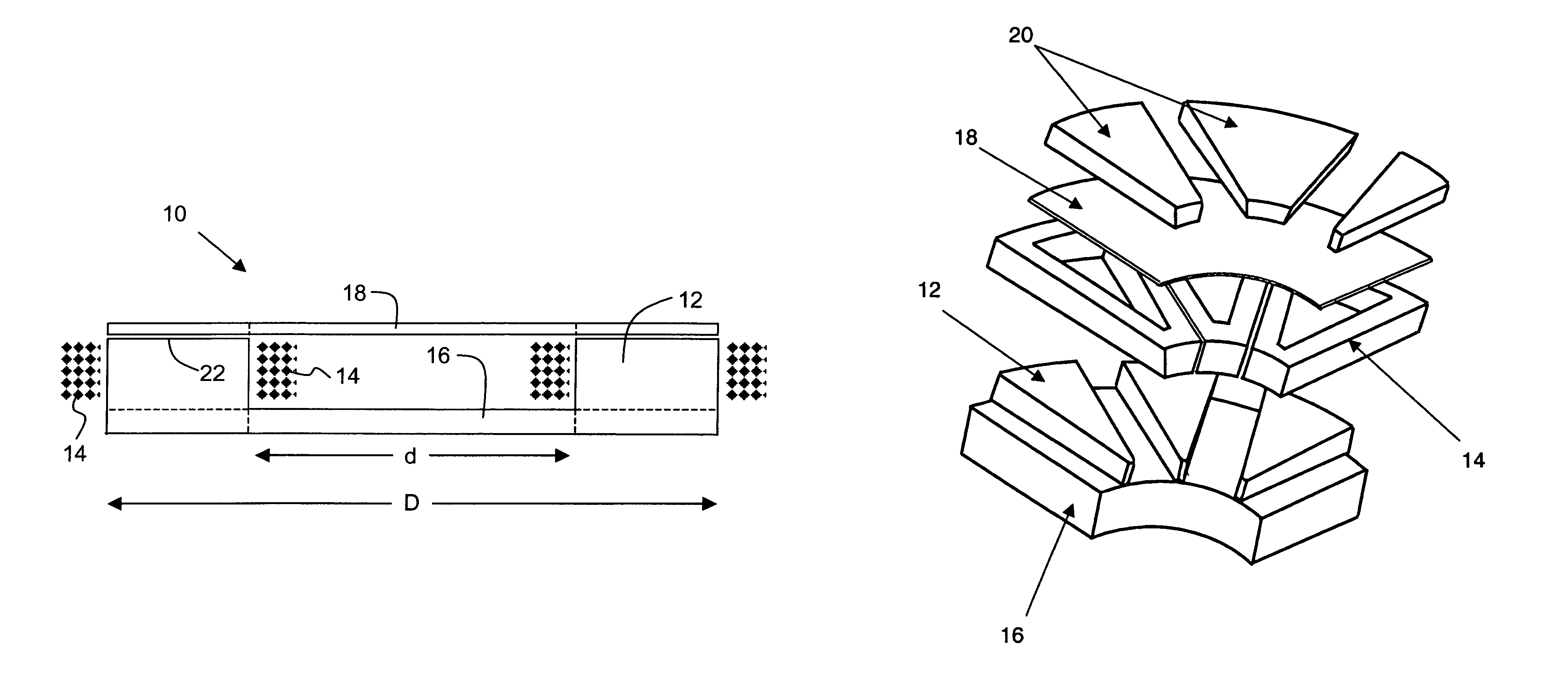
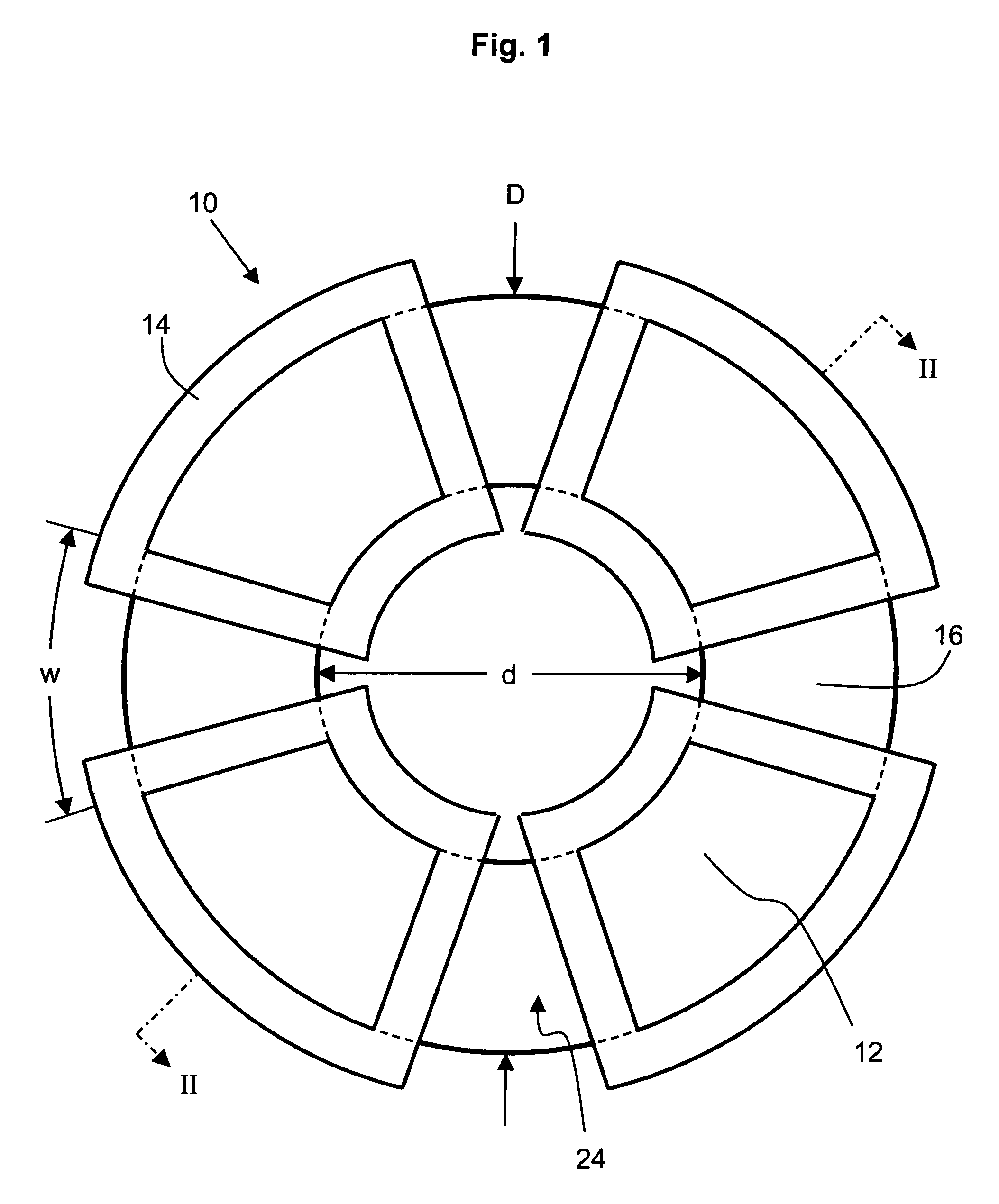
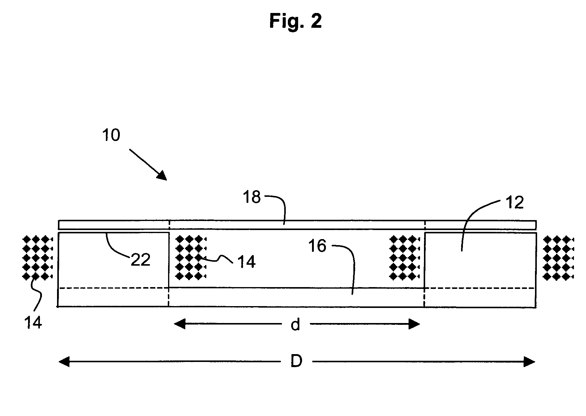
[0141]The machine includes one rotor and one stator and is a low pole count, high frequency, three phase electric device running as an actively rectified generator at 15 kRPM. The frontiron is constructed from METGLAS 2605SA1 amorphous metal wound as a toroid. The analysis is repeated for similar 100 kW power output electric devices with frontiron thickness ranging from 1.9 to 6.4 mm and compared with properties of a device without such a frontiron. The rotor is made of high energy product FeNdB permanent magnets housed in a carrier made of non-electrically-conductive composite, wh...


PUM


Abstract

A rotating, dynamoelectric machine, such as an electric motor, a generator, or a regenerative motor, comprises a stator assembly that includes a backiron section, a plurality of stator tooth sections, and a frontiron. The dynamoelectric machine has an axial airgap-type configuration. In addition, the electric machine has a high pole count that operates at high commutating frequencies, with high efficiency, high power density and reduced heating in the rotor. Low-loss materials employed in the dynamoelectric machine include amorphous metals, nanocrystalline metals, optimized Fe-based alloys, and optimized grain-oriented Fe-based materials or non-grain-oriented Fe-based materials.

Description

RELATED U.S. APPLICATION DATA[0001]This application claims the benefit of co-pending U.S. Provisional Application No. 60 / 509,222, filed Oct. 6, 2003, entitled “Efficient Axial Airgap Electric Device Having A Frontiron,” and Application Ser. No. 60 / 513,892, filed Oct. 21, 2003, entitled “Efficient High-Speed Electric Device Using Low-Loss Materials,” each of which applications is hereby incorporated in the entirety by reference thereto.BACKGROUND OF THE INVENTION[0002]1. Field of the Invention[0003]The invention relates to a dynamoelectric, rotating machine; and more particularly, to an axial airgap, dynamoelectric, rotating machine comprising a rotor assembly and a stator assembly that includes a frontiron section, a backiron section, and a plurality of stator tooth sections.[0004]2. Description of the Prior Art[0005]The electric motor and generator industry is continuously searching for ways to provide dynamoelectric, rotating machines with increased efficiencies and power densitie...

Claims


Application Information

Patent Timeline
Patent Type & Authority Patents(United States)
IPC IPC(8): H02K1/00H02K1/02H02K1/06H02K21/00H02K21/24
CPCH02K21/24H02K1/02H02K1/27B82Y40/00
Inventor SEMONES, BURLEY C.HIRZEL, ANDREW D.
Owner LIGHT ENGINEERING INC
Why Eureka
Try Eureka