
DC converter circuit with overshoot protection

a dc converter and circuit technology, applied in the field of dc/dc converters, can solve the problems of component cost, circuit size and power dissipation, component count, component cost, etc., and achieve the effect of reducing voltage overshoo

Inactive Publication Date: 2006-09-12
GM GLOBAL TECH OPERATIONS LLC
View PDF6 Cites 13 Cited by
  • Summary
  • Abstract
  • Description
  • Claims
  • Application Information

AI Technical Summary

Benefits of technology

The present invention is a DC-DC converter that has a unique design to improve its performance. It includes an input circuit that stores inductive energy and a transformer with a primary and secondary winding. The output circuit has four diodes and two capacitors to eliminate voltage overshoot. The input circuit also has two inductors and two switches to improve the efficiency of the converter. The technical effects of this invention are to reduce voltage overshoot, improve efficiency, and enhance the performance of the DC-DC converter.

Problems solved by technology

Disadvantages of the approach shown in FIGS. 3 and 4 relate to component count, component cost, circuit size and power dissipation.
Accordingly, disadvantages in circuit 500 also relate to component count, component cost, and circuit size.

Method used


Image

  • DC converter circuit with overshoot protection
  • DC converter circuit with overshoot protection
  • DC converter circuit with overshoot protection

Examples


Embodiment Construction

[0034]The following description of the preferred embodiment is merely exemplary in nature and is in no way intended to limit the invention, its application, or uses. For purposes of clarity, the same reference numbers will be used in the drawings to identify similar elements.

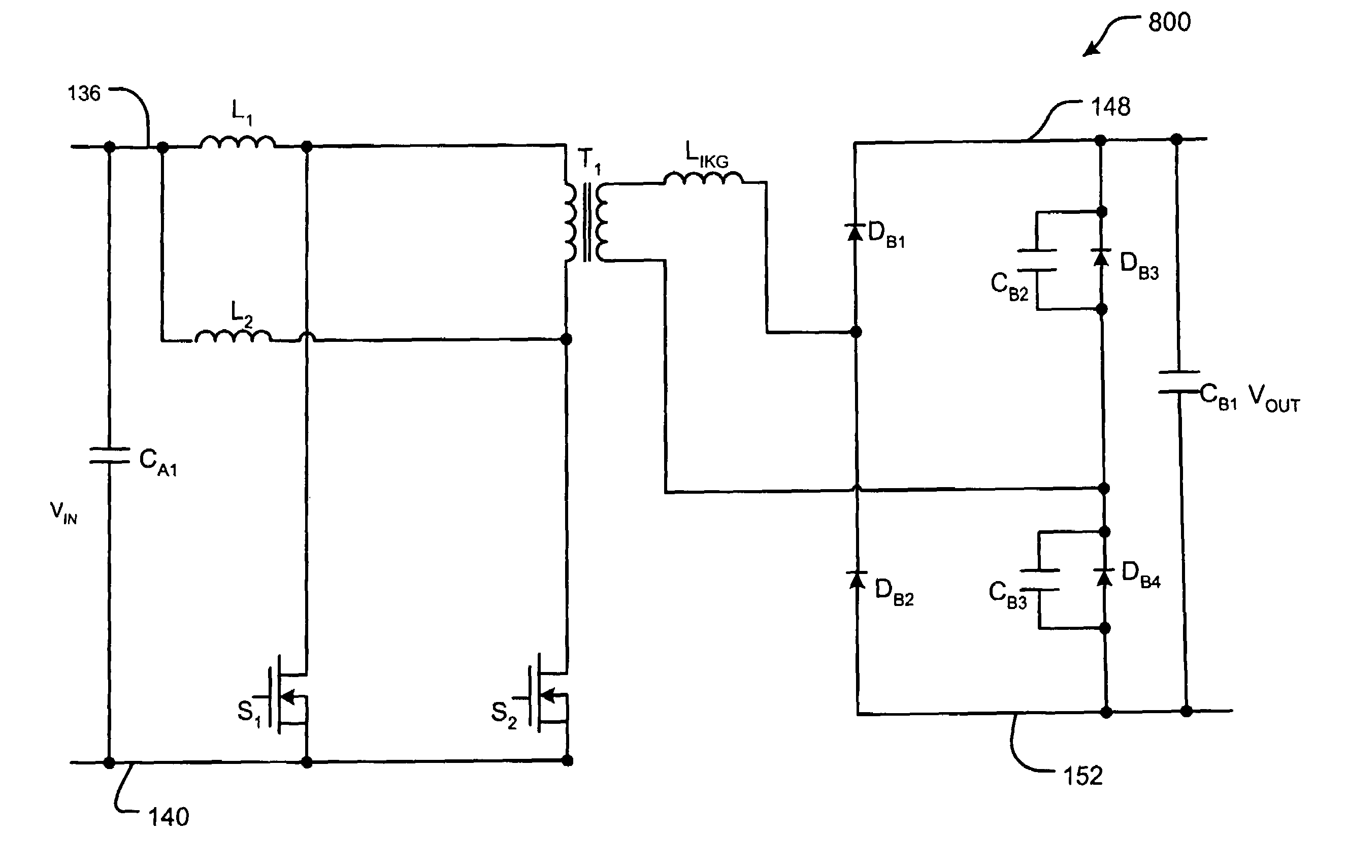
[0035]Turning now to FIG. 8, a DC / DC converter circuit 800 according to the present invention substantially reduces overshoot with fewer additional components than the approaches set forth in FIGS. 1–7. The circuit in FIG. 8 includes circuit elements from the DC / DC converter (without a snubber circuit) shown in FIG. 1. Additional circuit elements include a capacitor CB2 connected in parallel across the diode DB3. A capacitor CB3 is connected in parallel across the diode DB4.

[0036]The capacitors CB2 and CB3 provide additional snubber capacitance. In this regard, output capacitors of the semiconductor devices are, in one implementation, used as part of the snubber capacitors. The capacitors CB2 and CB3 control the...


PUM


Abstract

A DC-DC converter comprises an input circuit that stores inductive energy that includes a first switch that releases the stored inductive energy. A transformer includes a primary winding that communicates with the input circuit and a secondary winding. An output circuit communicates with the secondary winding and that includes first and second output conductors and a first diode that communicates with one end of the secondary winding and the first output conductor. A second diode communicates with one end of the secondary winding and the second output conductor. A third diode communicates with an opposite end of the secondary winding and the first output conductor. A fourth diode communicates with an opposite end of the secondary winding and the second output conductor. A first capacitor is connected in parallel to the third diode. A second capacitor is connected in parallel to the fourth diode.

Description

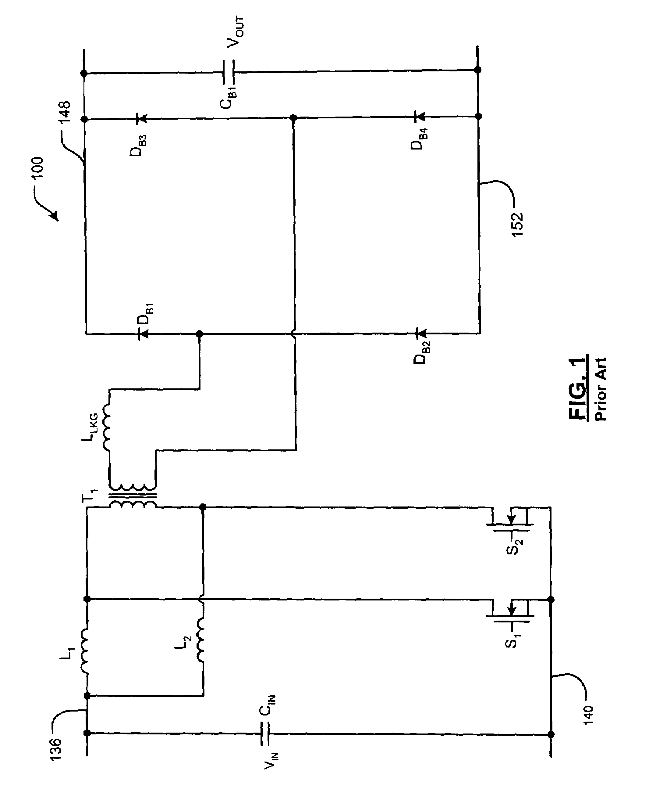
FIELD OF THE INVENTION[0001]The present invention relates to DC / DC converters, and more particularly to DC / DC converters with reduced voltage overshoot.BACKGROUND OF THE INVENTION[0002]Referring now to FIG. 1, an exemplary DC / DC converter 100 is shown. Voltage source VIN and capacitor Cin are connected across conductors 136 and 140. One end of an inductor L1 is connected to the conductor 136 and an opposite end is connected to one end of a primary winding of a transformer T1. One end of an inductor L2 is also connected to the conductor 136 and to the one end of the inductor L1. An opposite end of the inductor L2 is connected to an opposite end of the primary winding of the transformer T1.[0003]A first end of a switch S1 is connected to the opposite end of the inductor L1 and to the first end of the primary winding of the transformer T1. An opposite end of the switch S1 is connected to the conductor 140. A first end of a switch S2 is connected to an opposite end of the inductor L2 an...

Claims


Application Information

Patent Timeline
Patent Type & Authority Patents(United States)
IPC IPC(8): H02H7/125
CPCH02M3/33569H02M3/28
Inventor CHEN, KEMINGKAJOUKE, LATEEF A.LAZAR, JAMES F.
Owner GM GLOBAL TECH OPERATIONS LLC
Learn More