Voltage sense method and circuit which alleviate reverse current flow of current bi-directional converters

a current bi-directional converter and voltage sense technology, applied in the direction of electric variable regulation, process and machine control, instruments, etc., can solve the problems of cbs switch destruction, additional problems, and excessive current stress

Inactive Publication Date: 2005-02-08
TESLACO
View PDF5 Cites 25 Cited by
  • Summary
  • Abstract
  • Description
  • Claims
  • Application Information

AI Technical Summary

Problems solved by technology

Thus, when one of the parallel converters has started-up and reaches the full output voltage, the second to start converter with CBS switches effectively shorts the common output voltage resulting in large reverse current and in case of a number of parallel units results in excessive current stress and destruction of the CBS switches during the very start-up.
However, what appears to be a solution creates actually following additional problems, which are not resolved by the conventional methods such as Fixed Timing and Current Sense methods.
Another problem is that the output voltage common to two or more parallel units experiences voltage overshoot at instants when the synchronous rectifiers of each unit are enabled, once again due to effect of the body-diode voltage drop on output DC voltage.

Method used


Image

  • Voltage sense method and circuit which alleviate reverse current flow of current bi-directional converters
  • Voltage sense method and circuit which alleviate reverse current flow of current bi-directional converters
  • Voltage sense method and circuit which alleviate reverse current flow of current bi-directional converters

Examples


first embodiment

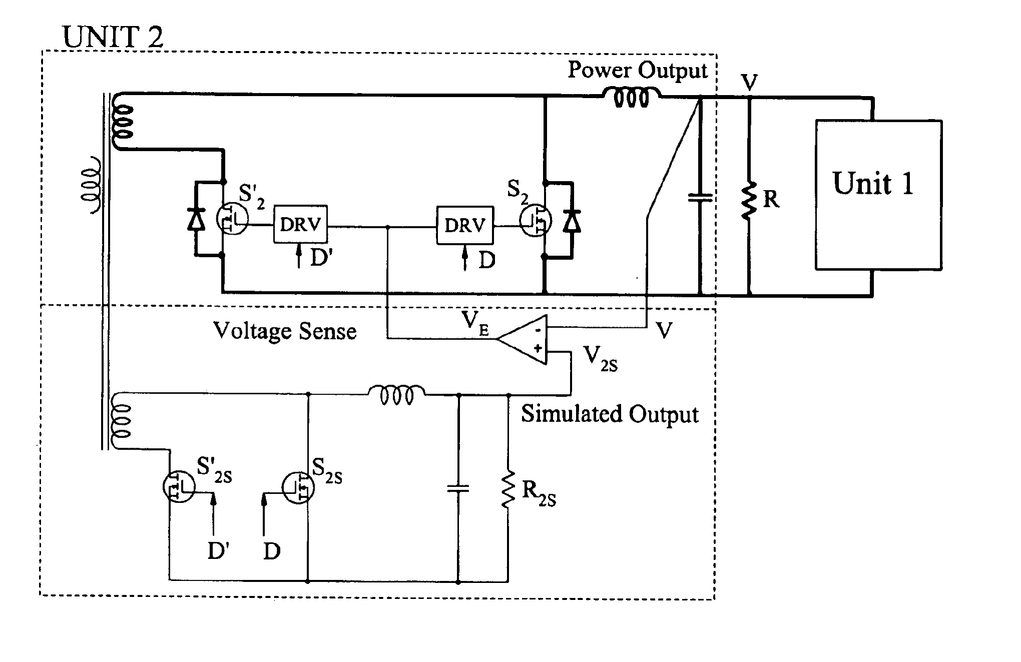
Although the internal Thevenin voltage source V2 is not directly accessible for measurement during the start-up of Unit 2, the same voltage can be indirectly measured by simulating this voltage with a simulated signal output V2S as shown in FIG. 16. The simulated output is created by use of an additional winding on the main transformer and a pair of small signal MOSFET devices S2S and S′2S to create with an additional small inductor and capacitor the auxiliary output V2S. Two signal MOSFET devices are operated out of phase and with the same duty ratios D and D′ as power output synchronous rectifier devices. However, unlike the power output devices which are disabled initially, the two signal MOSFET devices are always enabled as soon as primary devices are enabled. It is called simulated output since it simulates the time variation of the actual power output V2D if the power output were operated during start-up with its synchronous rectifiers enabled. The main power output is shown i...

second embodiment

The additional simulated output circuitry can be further simplified by connecting the outputs of the simulated output circuit and main power output together and therefore sense the differential voltage sense signal (V-V2) with reference to the main power output return lead, as shown in FIG. 20. This circuit still has additional complexity due to presence of extra transformer secondary winding and additional output inductor winding of the simulated output. Both, however, can be eliminated in a third embodiment of the present invention.

third embodiment

The two transformer secondary windings can be combined into single winding with the two signal processing MOSFET switches S2S and S′2S connected directly to the secondary winding of the main transformer providing power output. The output inductor of the simulated output can also be eliminated and the desired differential voltage sense signal (V-V2) sensed on the output capacitor CF of the simulated output with reference to the output voltage return (output ground). The two resistors are added in the drain lead of each auxiliary MOSFET to act as a low-pass filters to filter out the AC ripple, the role previously played by output inductor of simulated output. This third embodiment is one of the best modes to practice this invention since it implements the method of the present invention with a very simple signal processing circuit and without complicated additional magnetics windings and magnetics components, such as output inductor of simulated output.

This simple signal processing ci...


PUM


Abstract

The Voltage Sense Method is introduced and a number of its implementations using Voltage Sense Circuit are demonstrated to solve problems associated with the start-up of parallel switching converters, each converter having output synchronous rectifiers or more general Current Bi-directional Switches: prevention of the excessive reverse current, elimination of the excess voltage stress of the input switches and elimination of the voltage overshoot in the common output voltage. The Voltage Sense circuit added to each converter generates a Simulated Output Voltage, which predicts how would the output voltage of each particular unit rise during the start-up with enabled synchronous rectifiers if that particular unit were to operate alone. When the simulated output voltage of one converter reaches the actual common output voltage, synchronous rectifiers/CBS switches of that particular converter are all enabled so that their body-diodes, used up until that time to prevent reverse current flow, are by-passed eliminating all start-up problems. The introduced Voltage Sense Method and a number of its Voltage Sense Circuitries are also applicable to solve problems associated with the start-up of the current bi-directional converters with a battery load.

Description

FIELD OF THE INVENTIONThis invention relates to the field of switching DC-to-DC power conversion and in particular to parallel operation with current sharing of switching converters employing one or more synchronous rectifiers (MOSFETs) on their outputs and methods how to ensure smooth start-up with no overshoots.BACKGROUND OF THE INVENTIONThe demand for either higher output power from several smaller off-the-shelf power supplies or their fault-tolerant redundant operation in the case of critical loads, resulted in almost mandatory feature of switched mode power supplies: paralleling with current sharing. The parallel operation means that two or more power supplies are connected to the common source of power and deliver the power to the common load. When parallel operation of switching converter is mentioned, almost invariably the most common first question asked is: how is the load current shared between two converters? Clearly, equal sharing of the total current would be most desi...

Claims


Application Information

Patent Timeline
Patent Type & Authority Patents(United States)
IPC IPC(8): H02M3/158H02M3/04H02M3/335H02M3/24H02J1/10
CPCH02J1/102H02M3/33592H02M3/1584H02M1/36Y02B70/1475H02J1/001Y02B70/10
Inventor ZHANG, ZHE
Owner TESLACO
Why Eureka
Try Eureka