Cam type infusion regulator

A regulator, cam-type technology, applied in the direction of hypodermic injection instruments, etc., to overcome the deformation of the shell, save materials, and stabilize the speed

Inactive Publication Date: 2009-11-04
张亚平
View PDF1 Cites 11 Cited by
  • Summary
  • Abstract
  • Description
  • Claims
  • Application Information

AI Technical Summary

Problems solved by technology

[0005] Through searching, there is no technical solution of the same type (except computer control technology and other types) that can overcome or effectively solve the many shortcomings of the above-mentioned roller inclined plane infusion regulator at home and abroad.

Method used


Image

  • Cam type infusion regulator
  • Cam type infusion regulator
  • Cam type infusion regulator

Examples


no. 2 example

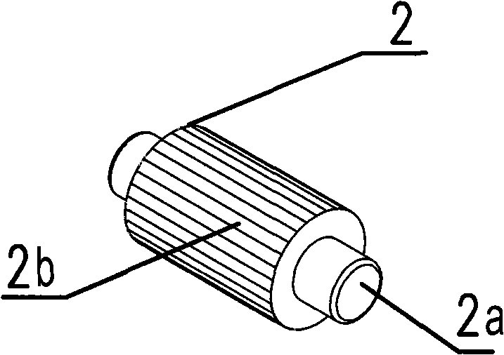
[0028] attached Figure 6 , is a structural schematic diagram (3A) and a half-section schematic diagram (3B) of the adjustment wheel of the second embodiment of a cam-type infusion regulator of the present invention. It can be seen from the figure that there are shafts 3a at both ends of the adjustment wheel 3, and the surface of the adjustment wheel 3c It is in the shape of a cam, and there are two circular adjustment wheels 3b with horizontal spines on the surface between the two sides and the shaft 3a, for finger rubbing and adjustment. The surface 3c of the adjustment wheel is gradually opened along the axis. The curved surface with a certain curvature change is designed in a linear manner, and its variation range meets the speed control requirements of a cam-type infusion regulator of the present invention. At the highest position of the curved surface, a transverse protrusion 3d is formed, so that the regulator can confirm that the adjustment is at the cut-off position ....


PUM


Abstract

A cam type infusion regulator consists of a shell 1, a supporting wheel 2 and a regulating wheel 3. The shell has a structure of a U-shaped groove, two pairs of axle holes (1a, 1c) are correspondingly drilled on the upper side and the lower side, and axial lines of the two pairs of the axle holes (1a, 1c) are parallel with each other and perpendicular with each other; the supporting wheel 2 is arranged in the axle hole 1c on the lower part of the shell; the regulating wheel 3 is arranged in the axle hole 1a on the upper part of the shell; the surface 3c of the regulating wheel has a cam shape, the distance between the surface 3c of the regulating wheel and an axle center changes in an involute mode, and the curvature change of the surface 3c of the regulating wheel meets the regulating and control requirements on the infusion speed; an infusion conduit is arranged between the regulating wheel 3 and the shell 1 and the supporting wheel 2; and during use, fingers twist the regulating wheel 3, the change of the distance between a curved surface 3c of the regulating wheel and a supporting wheel 3 on the bottom of the shell extrudes or releases the conduit, and changes the sectional area of the conduit to achieve the aim of regulating and controlling the infusion speed. Compared with the prior infusion regulator, the cam type infusion regulator has the characteristics of small size, material conservation, capability of self-assembly, improvement on the efficiency, convenient use, reliable regulation and stable speed.

Description

technical field [0001] The invention relates to an infusion speed regulator, in particular to a cam-type infusion speed regulator used in intravenous supplementation of medicinal liquid or liquid therapy. Background technique [0002] At present, the commonly used method to control the infusion speed in clinical practice at home and abroad is to install an inclined-plane regulator with a movable roller in the inclined slide on the outside of the infusion catheter. to adjust the infusion speed; however, due to its design, there are many turns in the shell structure, and its typical structure is shown in Figure 1: the shell K and the roller L form a roller inclined-plane regulator, and the axis of the roller L is in the horizontal direction provided by the shell K. Roll in the chute, and roll the infusion catheter on the inclined bottom surface K2 of the housing K to realize the adjustment process of changing the cross-sectional area of ​​the catheter; due to its design requir...

Claims


Application Information

Patent Timeline
Patent Type & Authority Applications(China)
IPC IPC(8): A61M5/175
Inventor 张亚平
Owner 张亚平
Why Eureka
Try Eureka