Bottom-reinforced filter bag ash removal method with variable inner channel and filter device

A filter device and inner channel technology, applied in separation methods, dispersed particle filtration, chemical instruments and methods, etc., can solve problems such as the decrease in the pressure rise rate of the filter bag, the decrease in the peak pressure of the filter bag, and the large filter area of ​​the filter bag. The effect of increasing the pressure peak and pressure rise rate, increasing the pressure rise rate in the filter bag, and reducing the area of ​​​​the equipment

Active Publication Date: 2020-08-18
SOUTHEAST UNIV
View PDF18 Cites 3 Cited by
  • Summary
  • Abstract
  • Description
  • Claims
  • Application Information

AI Technical Summary

Problems solved by technology

[0005] (1) Since the filter bag is in the form of a straight tube with the same upper and lower cross-sectional areas, after the dust removal airflow is introduced, the axial speed of the upper part of the dust removal airflow in the filter bag is relatively large, and when the axial direction moves downward, a part of the dust removal airflow passes through the filter bag, The flow of dust-cleaning air is reduced, the axial velocity of dust-cleaning airflow is reduced, the speed of pressure rise in the filter bag is reduced, and the effect of cleaning dust at the bottom of the filter bag is worse than that in the middle
In addition, the dust removal air flow at the lower part of the filter bag is small, while the cross-sectional area of ​​the channel inside the filter bag does not change, resulting in a drop in the peak pressure inside the filter bag, especially when the particles are easy to absorb moisture, the moisture content of the flue gas is large, and the length of the filter bag is large. Cleaning effect is poor
For example, the long filter bag dust collector used for waste incineration flue gas treatment has a high moisture content in the flue gas, and the phenomenon of particulate matter sticking to the filter bag often occurs at the bottom of the filter bag, which affects the dust removal effect and the normal operation of the equipment
[0006] (2) Generally, the filter bag filter area of ​​the bag filter is large, and the equipment manufacturing cost, installation and civil construction cost of the bag filter are relatively high. The existing filter bag is in the form of a straight cylinder, and the internal volume space of the filter bag is still relatively large, which is not used. get up, waste

Method used


Image

  • Bottom-reinforced filter bag ash removal method with variable inner channel and filter device
  • Bottom-reinforced filter bag ash removal method with variable inner channel and filter device
  • Bottom-reinforced filter bag ash removal method with variable inner channel and filter device

Examples


Embodiment 1

[0028] A bag bottom enhanced filter bag cleaning method with variable internal channels: take a filter bag and make the internal channel in the filter bag through which the cleaning air flow is variable, and the internal channel is variable to make the internal channel The cross-sectional area decreases from the opening of the filter bag to the bottom of the filter bag. When the cleaning airflow enters the filter bag and flows to the bottom of the filter bag, the cross-sectional area of ​​the channel in the filter bag is continuously reduced to continuously compress the cleaning airflow and increase The impact pressure and impact speed of the cleaning airflow strengthen the cleaning at the bottom of the filter bag, so that the dust particles stuck to the bottom of the filter bag can be removed.

[0029] In this embodiment, the filter bag adopts a W-shaped filter bag with a W-shaped axial interface, and uses a W-shaped filter bag with a large upper and a smaller W-shaped filter bag...

Embodiment 2

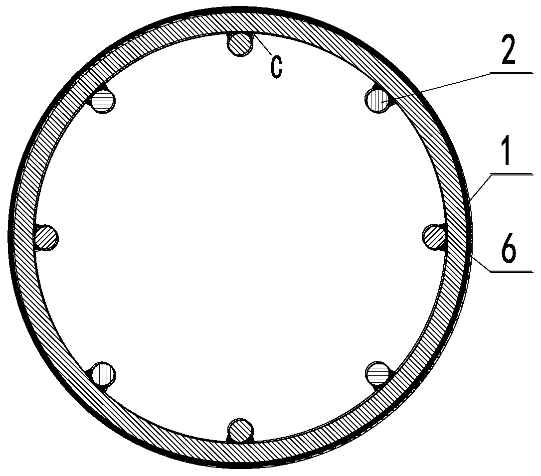
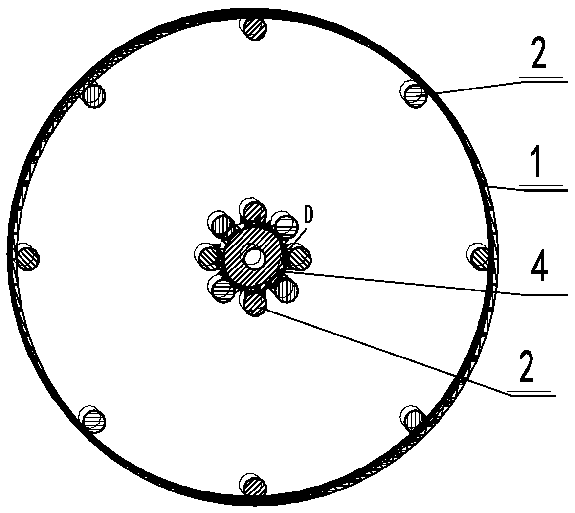
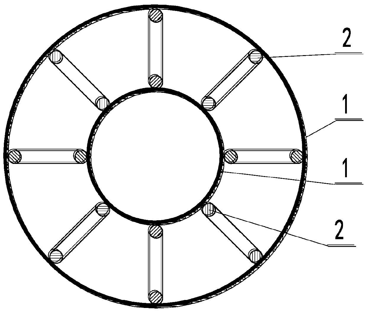
[0031] A filter device of a bag bottom reinforced filter bag dust cleaning method with a variable inner channel, comprising a cage frame and a frame pressing sleeve 6, a cloth bag is sheathed outside the cage frame and the cloth bag 1 is attached to the cage frame The cage frame includes a cohesive connector 4 and at least three V-shaped steel circles 2. One end of the V-shaped steel circle 2 is fixed to the cohesive connector 4 and encloses it to form a conical inwardly concave cavity. Figure 5 Specifically, one end of the V-shaped steel circle 2 can be welded to the position D of the cohesive connector 4, and the other end of the V-shaped steel circle 2 can be gathered in the frame compression sleeve 6. Refer to Image 6 Specifically, the other end of the V-shaped steel circle 2 can be welded to the C of the frame compression sleeve 6, a detachable cloth bag tensioning slider 3 is arranged in the conical inwardly concave cavity, and one end of the cloth bag 1 The other end of ...


PUM


Abstract

The invention discloses a bottom-reinforced filter bag ash removal method with a variable inner channel and a filter device, which are used for enhancing filter bag ash removal. The method comprises the following steps: introducing deashing airflow into the filter bag of which the cross section area of the inner channel is reduced along the direction from the filter bag opening to the bottom of the filter bag to flow into the bottom of the filter bag, and continuously reducing the cross section area of the inner channel of the filter bag to ensure that the filter bag continuously compresses the deashing airflow and improve the impact pressure and impact speed of the deashing airflow. The device comprises a cage framework and a framework pressing sleeve, wherein a cloth bag is arranged outside the cage framework in a sleeving manner and is attached to the cage framework; the cage framework comprises cohesion connecting pieces and at least three V-shaped steel rings, wherein one end of each V-shaped steel ring is fixed on the cohesion connecting piece to form a conical inward concave cavity; and a cloth bag tensioning sliding block is arranged in the conical inwards-concave cavity, wherein one end of the cloth bag is arranged on the framework pressing sleeve in a sleeving mode, the other end of the cloth bag is folded in the cloth bag tensioning sliding block; the cloth bag is embedded into the conical inwards-concave cavity along with the cloth bag tensioning sliding block and fastened by one end of the V-shaped steel rings.

Description

Technical field [0001] The invention relates to a dust removal method and a filter device for a bag bottom reinforced filter bag with a variable inner channel for a bag filter, which can enhance the dust removal effect and uniformity, increase the area of ​​the filter bag per unit volume, and reduce the bag dust removal The footprint and manufacturing cost of the device. Background technique [0002] Bag filter is the main and key equipment for the treatment of flue gas particulate matter. It has been industrially used for nearly a hundred years and has a great demand. Improvements in increasing the collection area per unit volume and enhancing the ash removal effect will produce a greater social economy benefit. [0003] Most of the existing bag filter adopts pulse cleaning, and there is also a small amount of atmospheric back blow cleaning. Both cleaning methods use the cleaning air flow. Its main function is to change the normal operation state and cause filtration. The instan...

Claims


Application Information

Patent Timeline
Patent Type & Authority Applications(China)
IPC IPC(8): B01D46/04
CPCB01D46/04B01D46/0001B01D2258/0283B01D46/02B01D46/60
Inventor 葛仕福
Owner SOUTHEAST UNIV
Why Eureka
Try Eureka