Moving platform on rail vehicle

a technology for moving platforms and rail vehicles, applied in railway bodies, transportation and packaging, roads, etc., can solve the problems of difficulty in performing the required duties of work, difficulty in completing the required work, and high cost of the system, so as to eliminate fatigue and stress on the operator.

Active Publication Date: 2011-05-26
HARSCO TECH
View PDF4 Cites 11 Cited by
  • Summary
  • Abstract
  • Description
  • Claims
  • Application Information

AI Technical Summary

Benefits of technology

[0011]In this configuration, the operator remains generally immobile in respect to the machine lurching forward. As the machine keeps moving forward, the platform is pulled backwards in respect of the machine while maintaining a generally consistent forward motion relative to the ground. As the machine is being decelerated to a stop, the rate and number of pulses of the encoder wheel cause the actuator controlling the platform position to push the operator station forward at variable adjustable rates. While the machine is stopped to perform the work, the platform keeps moving forward relative to the ground, generally, at the same speed as before. As the machine starts to index forward, the cycle of the platform is repeated. Thus, in relation to the ground, the platform is continually moving forward at a generally consistent speed. This system substantially eliminates fatigue and stresses on the operator, and it is adaptable to any type of rail vehicle with few modifications of the operator's platform.

Problems solved by technology

The operator is working in a very uncomfortable environment, subject to fatigue, stress and difficulty to perform the required duties of his work.
This system is normally employed on large machines and works in a satisfactory manner, however, the system is very expensive and cumbersome.
For example, two different machines and two drives are required, the system is not practical for smaller and lighter machines due to the additional weight required to achieve an effective tractive effort, and the system requires sophisticated electronics required to control the motion of the two segments relative to each other.
That is, without sophisticated electronics controlling the motion of the two segments, the two segments may collide and damage each other and / or injure an operator.

Method used


Image

  • Moving platform on rail vehicle
  • Moving platform on rail vehicle
  • Moving platform on rail vehicle

Examples


Embodiment Construction

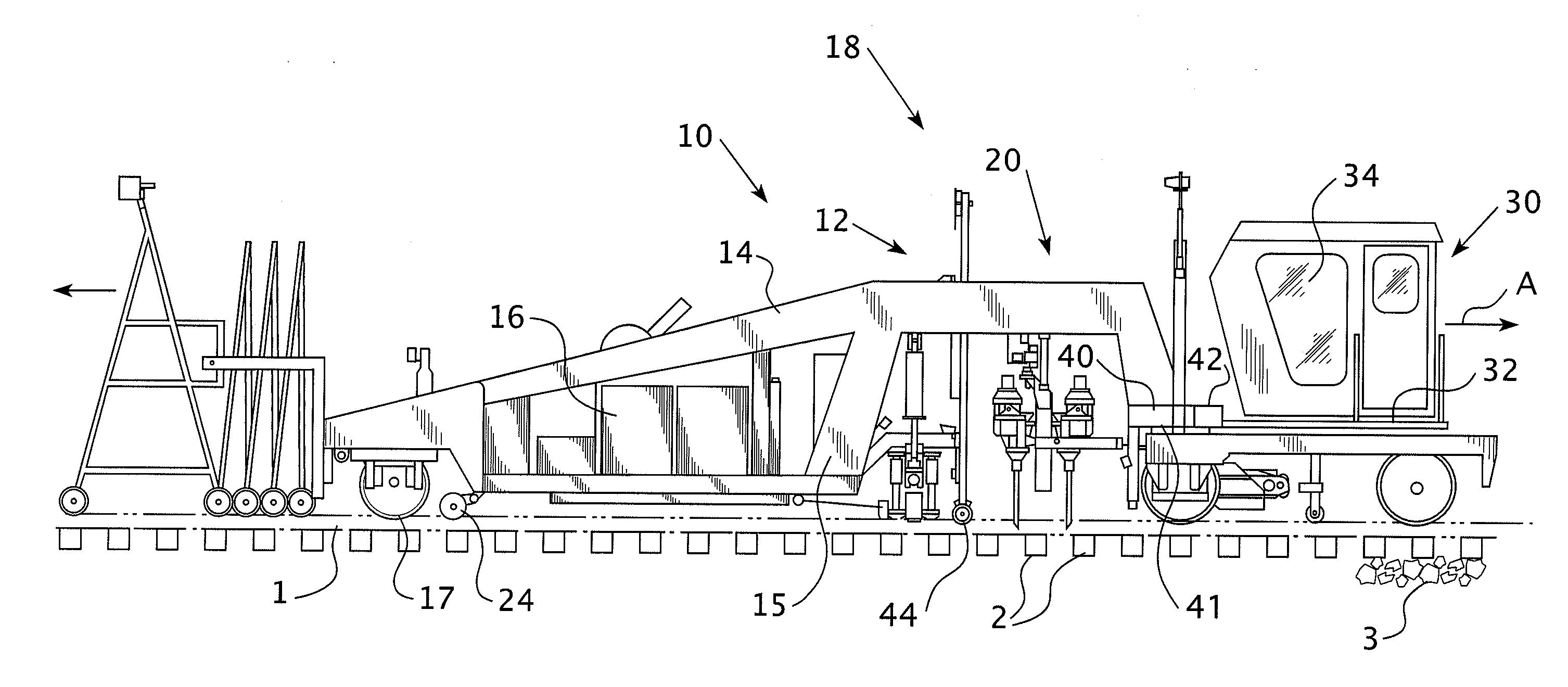
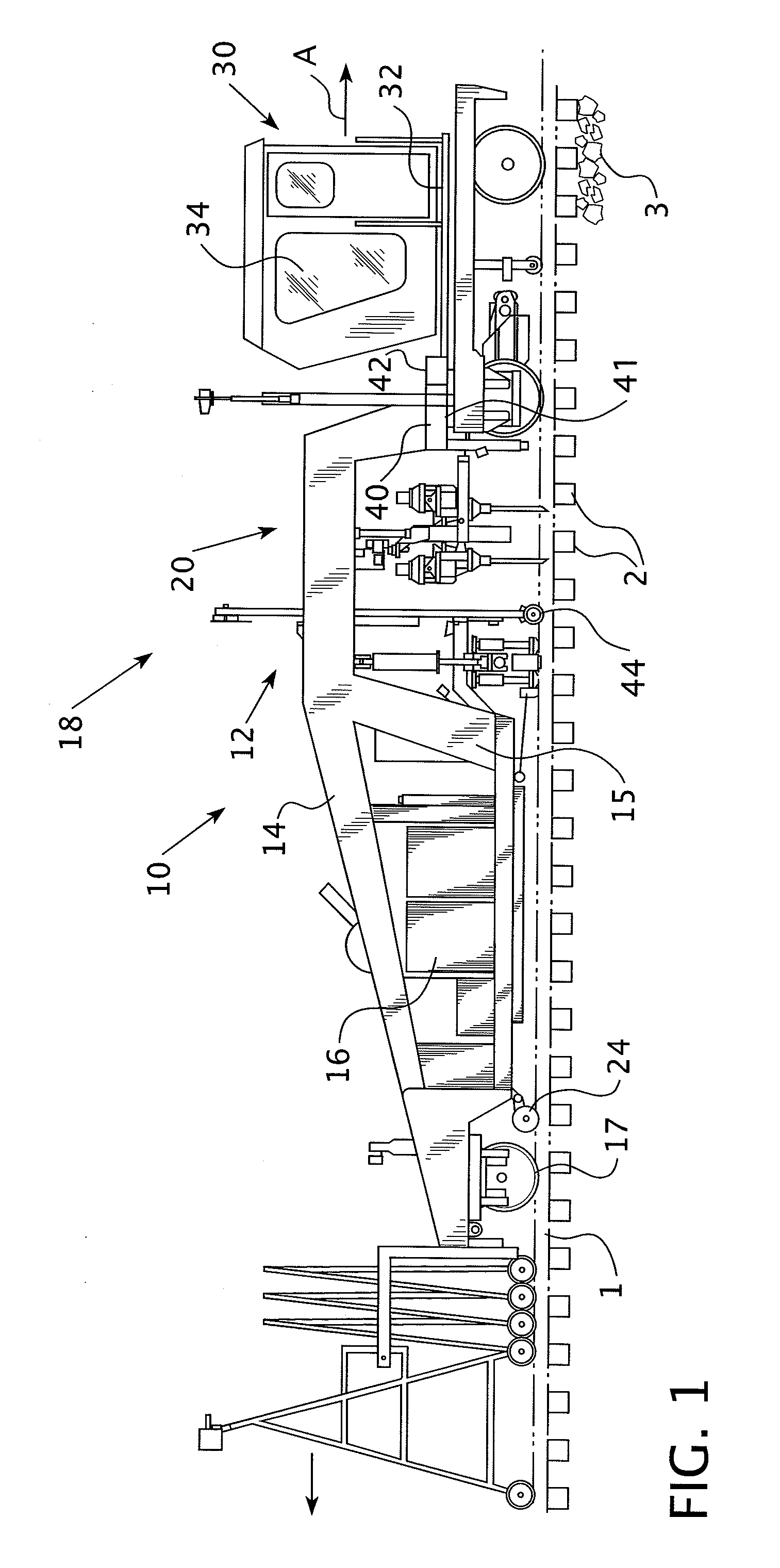
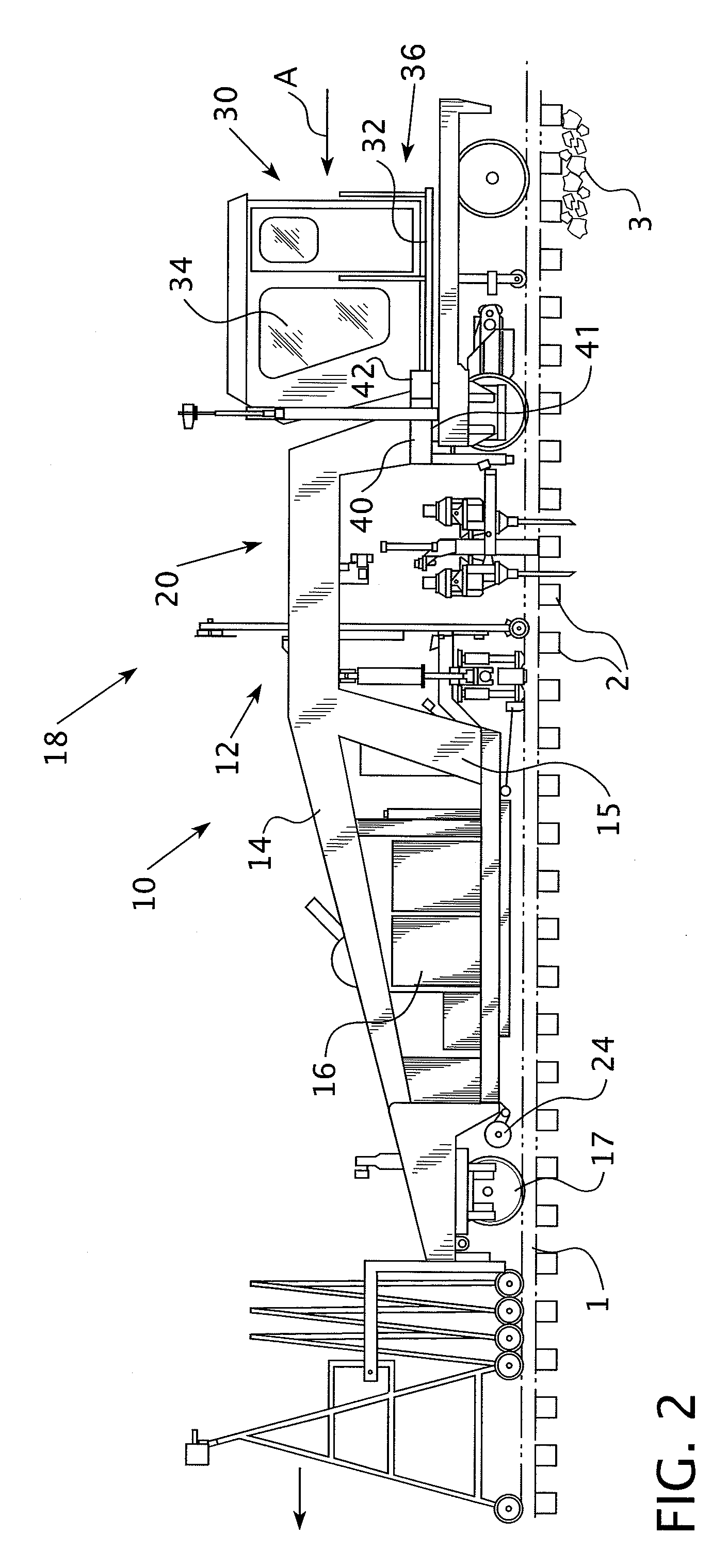
[0016]As used herein, a “single frame assembly” means that the frame assembly moves as a unit relative to a fixed point and that the front of the frame assembly is at a fixed distance from the back of the frame assembly. That is, while the frame assembly may have two or more parts that are articulated relative to each other, the frame assembly does not have distinct units or segments structured to travel on a pair of rails.

[0017]As used herein, “coupled” means a link between two or more elements, whether direct or indirect, so long as a link occurs. Unless otherwise noted, this does not include elements resting on, or supported by, a surface. For example, a seat in an automobile is coupled to the engine via the frame and other components. The seat is not, however, coupled to an adjacent automobile via the ground.

[0018]As used herein, “directly coupled” means that two elements are directly in contact with each other.

[0019]As used herein, “fixedly coupled” or “fixed” means that two co...


PUM


Abstract

A rail vehicle having a single frame assembly and a movable platform coupled thereto is provided. The rail vehicle indexes, i.e. advances intermittently, along railroad rails. The movable platform advances in a single direction at a generally steady speed as the rail vehicle indexes along a railroad. The platform is the floor of, or a base for, a cabin preferably having a seat, roof support, and controls for the operator. The platform rides longitudinally with the machine on rollers or slides, thus separating the operator and controls from the rest of the machine. Thus, while the rail vehicle moves in an abrupt stop-and-go manner, the platform and the operator move generally consistently in a single direction.

Description

CROSS REFERENCE TO RELATED APPLICATION[0001]This application claims priority under 35 U.S.C. §119(e) to U.S. Provisional Patent Application Ser. No. 61 / 001,413, filed Nov. 1, 2007 entitled, Continuous moving platform on rail vehicle.FIELD OF THE INVENTION[0002]This application relates to railroad maintenance vehicles and, more specifically to a railroad maintenance vehicle having a platform that moves generally continuously at one speed and in one direction while the rail vehicle repeatedly starts and stops at short intervals.BACKGROUND INFORMATION[0003]Generally, a railroad includes at least one pair of elongated, substantially parallel rails coupled to a plurality of laterally extending ties and which are disposed on a ballast bed. The rails are coupled to the ties by metal tie plates and / or spring clips. The ballast is a hard particulate material such as, but not limited to, gravel. Ties may be made from either concrete or wood. The ballast filled space between ties is called a c...

Claims


Application Information

Patent Timeline
Patent Type & Authority Applications(United States)
IPC IPC(8): B61D15/00
CPCE01B27/16B61D15/00
Inventor DELUCIA, ANTHONY P.MILLER, ROBERT S.
Owner HARSCO TECH
Why Eureka
Try Eureka