Optical fiber drop cables

a technology of optical fiber drop cable and drop cable, which is applied in the direction of conductors, instruments, electrical equipment, etc., can solve the problem of not being able to conduct a relatively low voltage electrical supply

Inactive Publication Date: 2006-09-12
PRYSMIAN CABLES & SYST
View PDF26 Cites 98 Cited by
  • Summary
  • Abstract
  • Description
  • Claims
  • Application Information

AI Technical Summary

Problems solved by technology

However, this cable is intended for underground routing and not for suspension installation.
Furthermore, it is not suita

Method used


Image

  • Optical fiber drop cables
  • Optical fiber drop cables
  • Optical fiber drop cables

Examples


Embodiment Construction

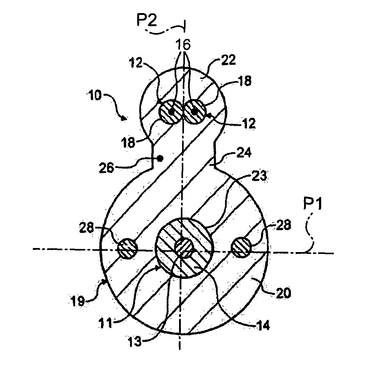
[0017]FIG. 1 shows an optical fibre drop cable 10 containing a buffered optical fibre 11 and two insulated electrical conductors 12. The buffered optical fibre 11 comprises an optical fibre 13 and a plastics coating 14 that protects the surface of the fibre 13 from scratching and abrasion. The plastics coating may for example be a nylon coating and the fibre with coating will typically have a diameter of approximately 1 mm. The insulated conductors 12 comprise copper wires 16 encapsulated in a colour-coded electrical insulating coating 18, which may be of any suitable material as will be well known to those skilled in the art. Typically, the copper wires will have a diameter of approximately 0.4 mm and the outside diameter of the insulating coating will typically be approximately 1.2 mm One insulated conductor 12 is to serve as the live wire and the other as a neutral / earth wire in a circuit that will typically carry 9 to 12 volts for powering a telephone connected with the cable. I...


PUM


Abstract

An optical fibre drop cable for suspension installation includes sheathing having a first portion containing a strengthening arrangement for supporting the cable in a suspension installation and a second portion that is separable from the first portion. The second sheathing portion contains a plurality of electrical conductors. The first sheathing portion defines at least one passage for optical fibers.

Description

CROSS REFERENCE TO RELATED APPLICATIONS[0001]This application is a national phase application based on PCT / GB02 / 05153, filed Nov. 15, 2002, the content of which is incorporated herein by reference, and claims the priority of European Patent Application. 01309727.4, filed Nov. 19, 2001.BACKGROUND OF THE INVENTION[0002]1. Field of the Invention[0003]The invention relates to optical fibre drop cables for use in telecommunications systems and particularly, but not exclusively, to such cables for use in connecting between a customer's premises and a connection point common to a number of such customers.[0004]2. Description of the Related Art[0005]In the field of telecommunications networks, typically cables run from an exchange to a cabinet mounted at street level and from this cabinet cables are led to a customer's premises, usually by way of an aerial, or suspension installation comprising a cable suspended in catenary from poles or surrounding buildings. These aerially suspended cable...

Claims


Application Information

Patent Timeline
IPC IPC(8): G02B6/44H01B11/22G02B6/46G02B6/48H01B7/00H01B7/18H02G3/04
CPCH02G3/0487G02B6/483G02B6/4416
Inventor SUTEHALL, RALPHDAVIES, MARTIN VINCENT
Owner PRYSMIAN CABLES & SYST
Why Eureka
Try Eureka