

Defining parameters for a finite elements analysis calculation in a computer-assisted drafting program
Active Publication Date: 2006-09-12
AUTODESK INC
View PDF9 Cites 23 Cited by
- Summary
- Abstract
- Description
- Claims
- Application Information
AI Technical Summary
Benefits of technology
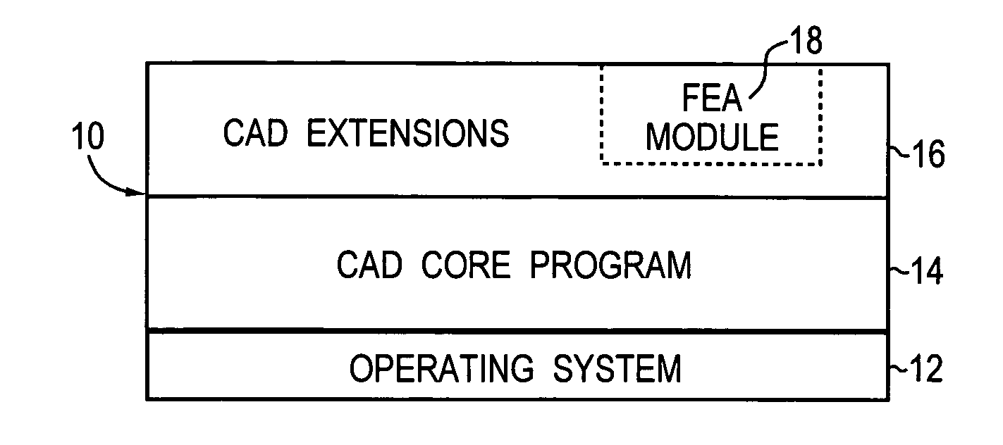
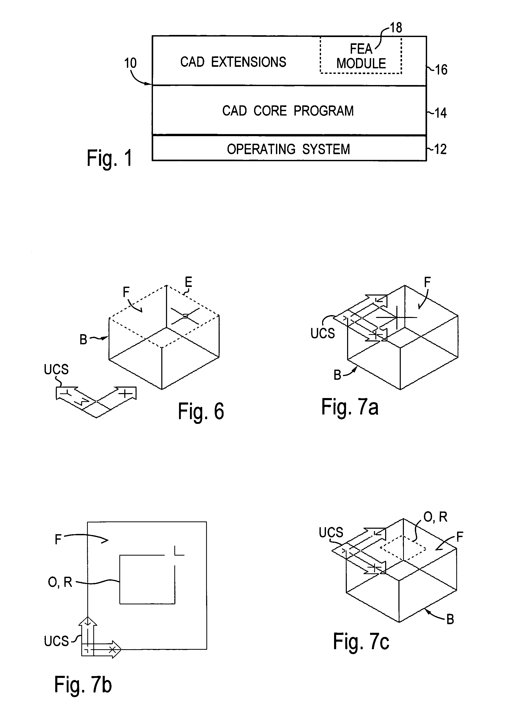
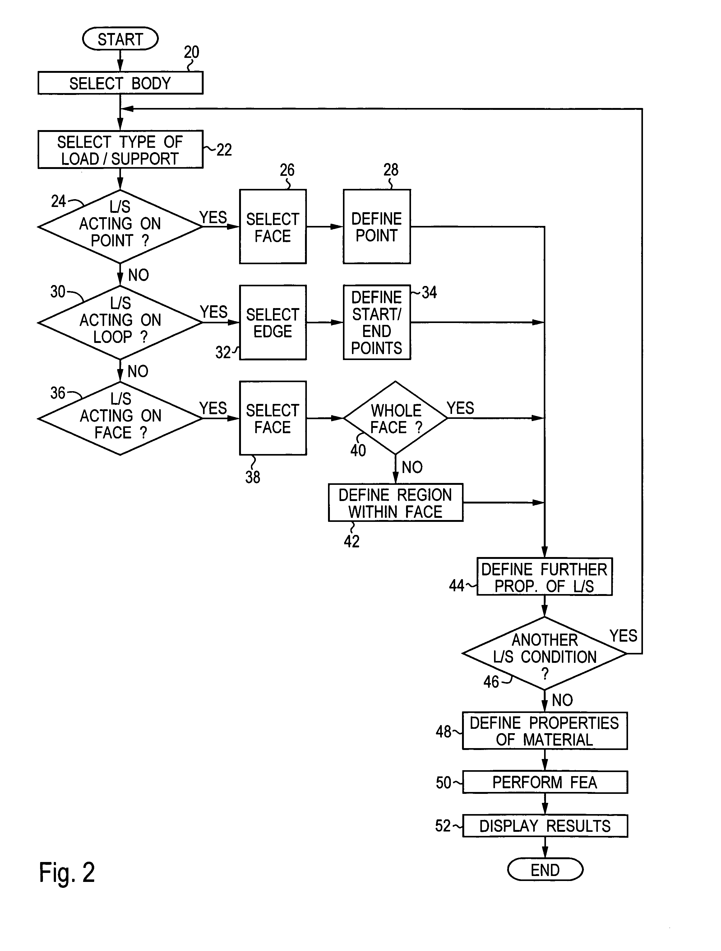
[0012]A basic idea of the present invention is that at least one graphical function of the CAD program is used to define a region within a face of a body for which an FEA parameter is to be entered. This region is then used to define a load/support condition for the FEA calculation. For example, it may be defined that a fixed or movable support or a load acts on the defined region or on the portion of the face outside the defined region. In this respect, the wording “region within a face” means that the present invention makes it possible for the user to define regions that do not comprise the whole face. A “face” of a body is generally understood (as defined in the boundary representation model) to be a portion of the surface of the body delimited by edges, or the whole surface of the body if there are no edges (e.g. for spheres or tori). A “load/support c
Problems solved by technology
For many available FEA programs, the definition of the input parameters is a rather cumbersome process.
While it is normally possible to import data defining the body to be analyzed from a CAD program, load and support parameters must be defined in a complex way.
In other words, there is often too little compatibility and integration between independent CAD and FEA programs.
However, the Genius Desktop 3 product impo
Method used
View moreImage
Smart ImageViewing Examples

Examples
 PUM
 Abstract
A method for defining at least one parameter for a finite elements analysis (FEA) calculation in a computer-assisted drafting (CAD) program comprises the steps of determining a body for which said parameter is to be defined, said body being a entity processed by said CAD program; and using at least one graphical function of said CAD program to define a region within a face of said body, said region being used to define a load/support condition for said FEA calculation. A computer program product and an apparatus comprise corresponding features. The present invention provides an improved way of defining parameters like load or support conditions for an FEA calculation in a CAD program.
Description
CROSS-REFERENCE TO RELATED APPLICATIONS[0001]This application claims priority under 35 U.S.C. §119 to European patent application No. 99-117-379.0, filed Sep. 3, 1999, by Peter Hummel, Igor Jacak, and Stanislav Hutnan, and entitled “DEFINING PARAMETERS FOR AN FEA CALCULATION IN A CAD PROGRAM,” which application is incorporated by reference herein.BACKGROUND OF THE INVENTION[0002]1. Field of the Invention[0003]The present invention concerns the fields of computer aided design (CAD) and finite elements analysis (FEA). In particular, the present invention concerns a way of improving the integration of these fields into a unified design environment.[0004]2. Description of Related Art[0005]The use of computer aided design (CAD) techniques has become common engineering practice. The available CAD programs range from simple drawing tools to sophisticated systems covering the whole range of product design and possibly further aspects like engineering or manufacturing or quality control. The...
Claims
Login to View More Application Information
Patent Timeline
 IPC IPC(8): G06F7/60G06F19/00G06F17/50G06T19/00
CPCG06F30/23G06T19/00
InventorHUMMEL, PETERJACAK, IGORHUTNAN, STANISLAV
OwnerAUTODESK INC