Mower suspension system and method

a suspension system and lawnmower technology, applied in transportation and packaging, agriculture tools and machines, agriculture, etc., can solve the problems of many conventional lawnmowers suffering from scalping and uneven cutting, and achieve the effects of reducing the movement of the frame, reducing the scalping and uneven cutting, and reducing the roll and pitch of the fram

Inactive Publication Date: 2006-09-19
FERRIS A DIV OF SIMPLICITY MFG
View PDF17 Cites 38 Cited by
  • Summary
  • Abstract
  • Description
  • Claims
  • Application Information

AI Technical Summary

Benefits of technology

[0013]As described above, many conventional lawn mowers suffer from scalping and uneven cutting problems when the lawn mowers traverse uneven surfaces. Some embodiments of the present invention substantially reduce scalping and uneven cutting by suspending each of the front wheels independently from the front frame of the lawn mower with the structure described above. Upon wheel contact with uneven ground such as a steep upward or downward grade, the front wheels are therefore able to move generally vertically without greatly altering the relationship of the frame with respect to the surface traversed, or at least with reduced movement of the frame. In this manner, roll and pitch of the frame can be significantly reduced, resulting in a higher-quality cut and an improved ride.
[0014]By employing a two-arm spring suspension assembly connected as described above, the inventors have discovered that far less damaging vibration, shock, and impact received by the front wheels are transmitted to the frame and to the operator. By reducing the transmission of such vibration, shock, and impact shock to the frame, the life of the lawn mower is considerably extended and the need for maintenance and repair is decreased.
[0016]In these and other embodiments, the front and / or rear suspension systems can be independent, and can be connected to a beam, subframe, or other structure that is pivotably coupled to the mower frame, thereby transmitting upward and downward force to the independent suspensions as well as to the pivoting beam, subframe, or other structure. Regardless of whether the cutter deck is also connected to these independent suspensions, this arrangement can result in improved suspension and cutter deck movement.
[0017]Due to decreased vibration, shock, and impact transmitted by various embodiments of the present invention, a lawn mower provided with a suspension according to some embodiments of the present invention can be operated at quicker speeds, resulting in increased lawn mower efficiency and decreased time needed to cut a surface. Also, the relatively simple design of some wheel suspensions according the present invention enables the suspension to be included in lawn mowers with little impact upon manufacturing and sales costs.

Problems solved by technology

As described above, many conventional lawn mowers suffer from scalping and uneven cutting problems when the lawn mowers traverse uneven surfaces.

Method used


Image

  • Mower suspension system and method
  • Mower suspension system and method
  • Mower suspension system and method

Examples


Embodiment Construction

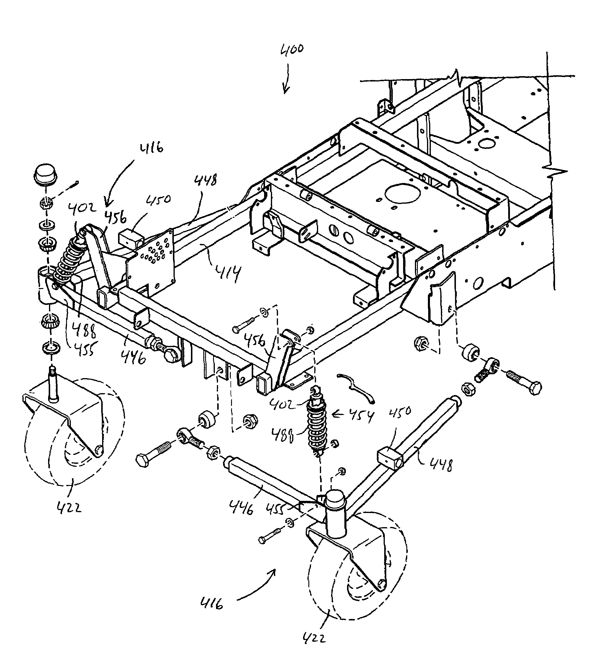
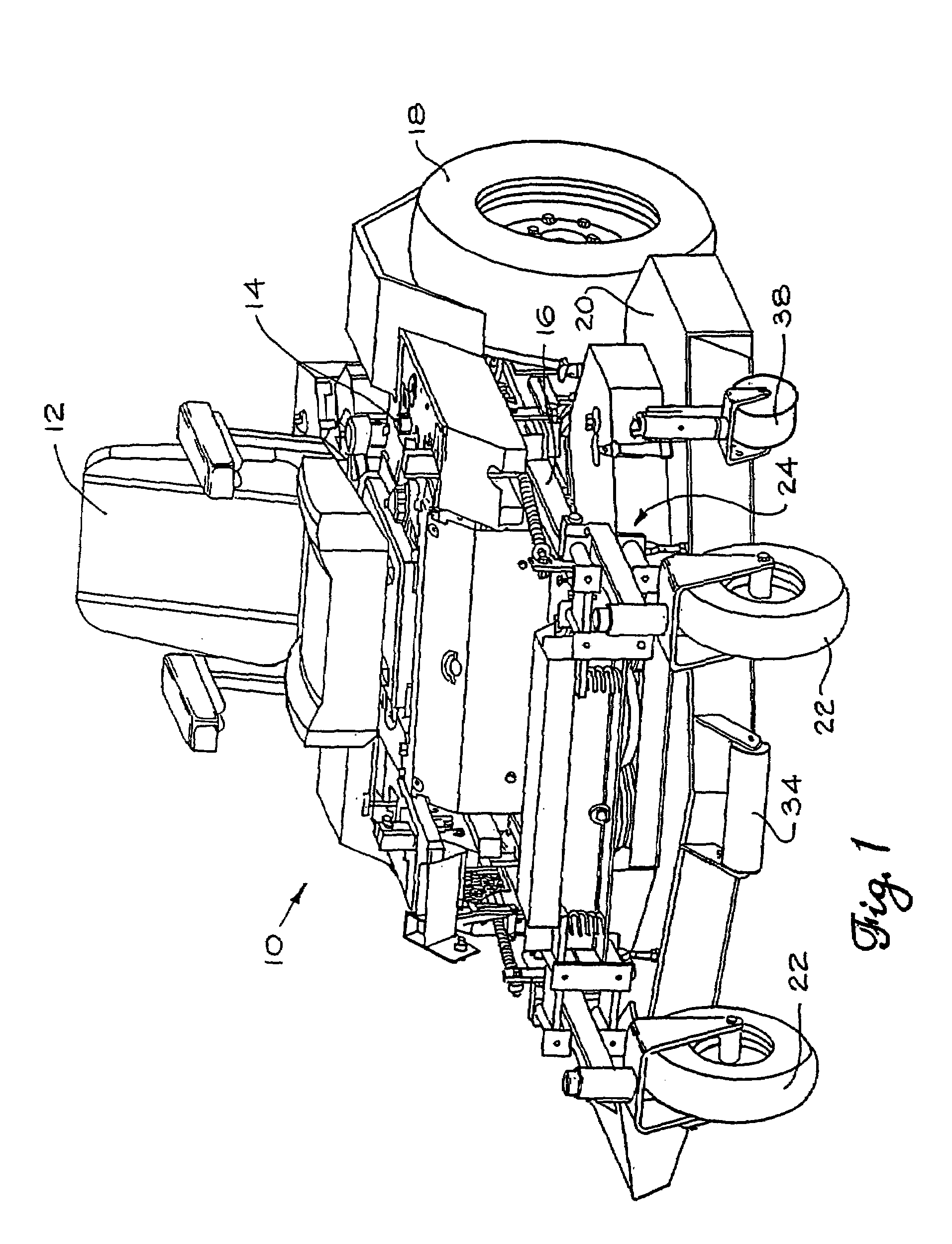
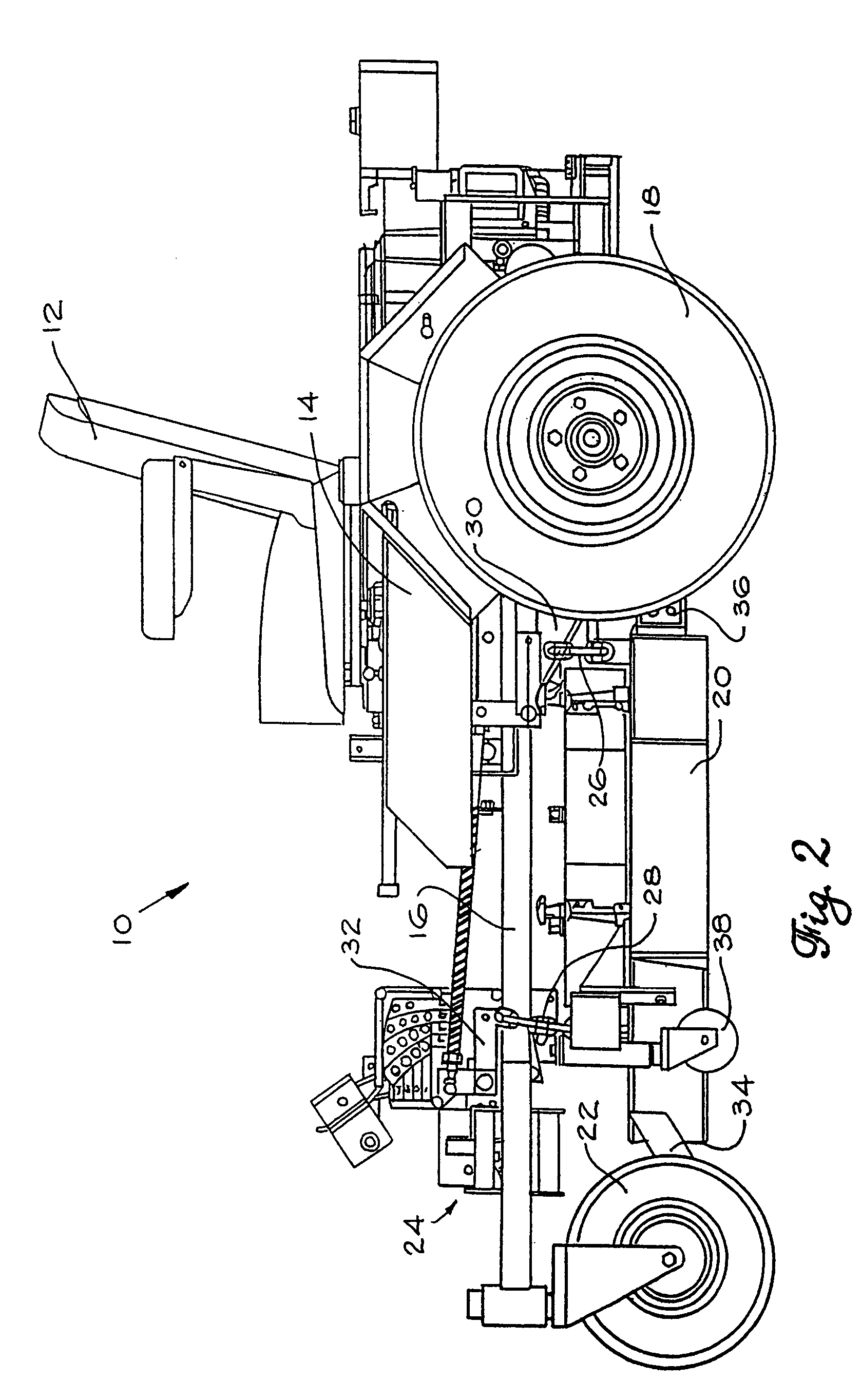
[0084]Referring to FIGS. 1–2, a lawn mower 10 includes a seat 12 connected to a chassis 14. Chassis 14 in turn rests on a main frame 16. Two rear wheels 18 are connected to main frame 16 by the independent suspension (not shown) as described in co-pending U.S. patent application Ser. No. 09 / 119,818. Two front wheels 22 are connected to main frame 16 via a front suspension system, shown generally at 24. A floating cutter deck 20 is preferably suspended beneath main frame 16 by rear suspension chains 26 and front suspension chains 28. Each rear suspension chain 26 is preferably connected to a rear wheel bracket 30 which is “wheel-side” of the rear independent suspension system. Each front suspension chain is preferably connected to a deck height adjustment mount 32 which is part of front suspension section 24. Suspending cutter deck 20 from the “wheel-side” of the front and rear independent suspensions ensures that cutter deck 20 moves vertically up and down in response to the vertica...


PUM

PropertyMeasurementUnit
lengthaaaaaaaaaa
widthaaaaaaaaaa
lengthaaaaaaaaaa

Abstract

A mower including a frame having a front portion, a rear portion, and at least one central longitudinal beam. The at least one beam is parallel with a longitudinal axis passing from the front portion to the rear portion of the frame. First and second wheels are positioned on opposite sides of the front portion of the frame and are spaced to define a track width of the mower, with the track width being a distance between a center portion of each of the first and second wheels. The first and second wheels pivot about a first longitudinal pivot axis and a second longitudinal pivot axis, respectively. The first and second longitudinal pivot axes are laterally spaced from the longitudinal axis between about 0% and about 20% of the track width.

Description

RELATED APPLICATIONS[0001]This is a continuation-in-part of U.S. patent application Ser. No. 10 / 285,350 filed on Oct. 31, 2002 now U.S. Pat. No. 6,857,254, which is a continuation-in-part patent application of U.S. patent application Ser. No. 09 / 879,800 filed on Jun. 12, 2001 and issued as U.S. Pat. No. 6,510,678, which is a continuation of U.S. patent application Ser. No. 09 / 384,534 filed on Aug. 27, 1999 and issued as U.S. Pat. No. 6,244,025, which in turn is a continuation-in-part of U.S. patent application Ser. No. 09 / 359,537 filed on Jul. 22, 1999 and issued as U.S. Pat. No. 6,460,318, which in turn is a continuation-in-part patent application of (i) U.S. patent application Ser. No. 09 / 144,499, filed Aug. 31, 1998 and issued as U.S. Pat. No. 5,946,893, which in turn claims benefit from U.S. Provisional Patent Application Ser. No. 60 / 063,362 filed on Oct. 28, 1997; (ii) U.S. patent application Ser. No. 09 / 119,818 filed on Jul. 21, 1998 and issued as U.S. Pat. No. 6,170,242, whic...

Claims


Application Information

Patent Timeline
Patent Type & Authority Patents(United States)
IPC IPC(8): A01D34/03A01D34/43A01D34/64B60B33/00B60G3/01B60G3/18B60G11/16
CPCA01D34/64B60B33/0005B60B33/0021B60B33/0039B60B33/0049B60B33/0057B60B33/0068B60B33/0073B60G3/01B60G3/18B60G11/16A01D34/661Y10T29/49904A01D2101/00B60G2200/144B60G2204/124B60G2204/148B60G2204/4232B60G2206/50B60G2300/084Y10T29/49622Y10T29/49826
Inventor MELONE, MARK J.DECKER, WILLIAMCROSSWAY, BRIANMARSHALL, JAMESMARSHALL, FRANK
Owner FERRIS A DIV OF SIMPLICITY MFG
Why Eureka
Try Eureka