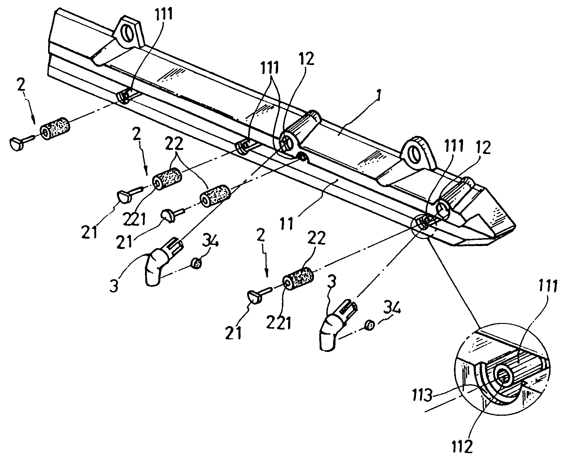
Sliding rail assembly for wire basket

a technology of sliding rails and wire baskets, which is applied in the direction of display hangers, dismountable cabinets, cabinets, etc., can solve the problems of increased friction, more severe abrasion, and difficult sliding of wire baskets ab>1/b>, and achieves less abrasion

Inactive Publication Date: 2006-09-19
LIN RUEI HSING
View PDF11 Cites 118 Cited by
  • Summary
  • Abstract
  • Description
  • Claims
  • Application Information

AI Technical Summary

Benefits of technology

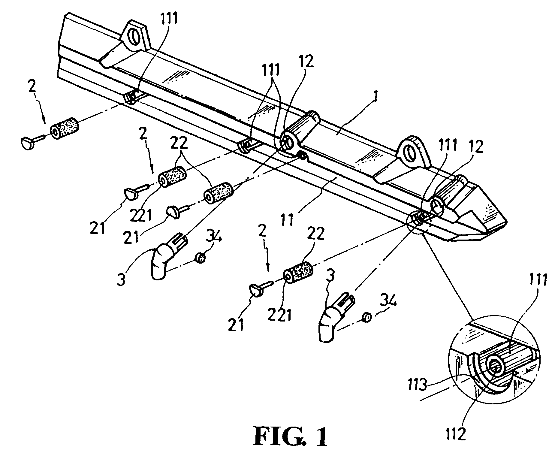
[0009]One of the major characteristics of the present invention is that the rail of the present invention has an enlarged opening in the front so that a wire basket could be guided into the rail quickly and easily.
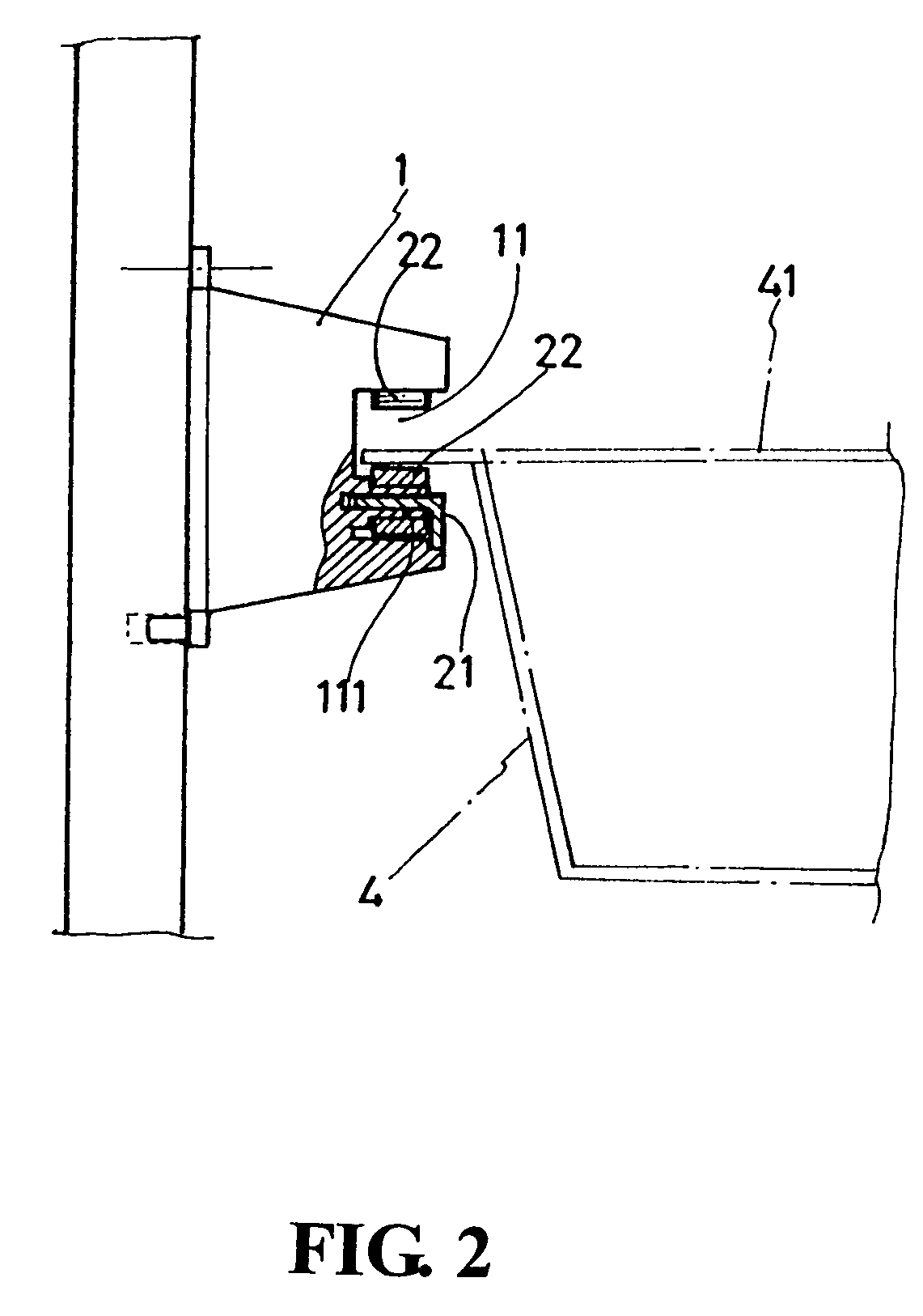
[0010]Another major characteristic of the present invention is that wheel members are installed along the bottom of the rail to provide both support and sliding functions to the wire basket. It is therefore much less abrasion and squeaking noise are generated when the wire basket is pushed or pulled along the rail. One additional wheel member is installed at the top of the rail in a front section to help guiding the wire basket gradually into a horizontal position.
[0011]A third characteristic of the present invention is that specially designed blocking members are installed along the rail so as to prevent the wire basket from being pulled entirely out of the rail, or being pushed too far into the rail.

Problems solved by technology

In addition, there are usually unpleasant loud squeaking noises when the wire basket A1 is slid.
Secondly, when the wire basket A1 is loaded with heavy items, the sliding movement of the wire basket A1 becomes more difficult from the increased friction.
The heavy weight would also cause even more severe abrasion.
Thirdly, as there is no positioning mechanism in the design of the conventional wire basket A1, the supporting rail A21, and the rail frame A2, the wire basket A1 could be pulled entirely out or pushed too far into the rail, increasing its difficulty of use.
Further more, if the wire basket A1 is filled with sharp knives or heavy tools, pulling out the entire wire basket A1 could pose a security hazard to the users, especially children.

Method used


Image

  • Sliding rail assembly for wire basket
  • Sliding rail assembly for wire basket
  • Sliding rail assembly for wire basket

Examples


Embodiment Construction

[0022]The following descriptions are of exemplary embodiments only, and are not intended to limit the scope, applicability or configuration of the invention in any way. Rather, the following description provides a convenient illustration for implementing exemplary embodiments of the invention. Various changes to the described embodiments may be made in the function and arrangement of the elements described without departing from the scope of the invention as set forth in the appended claims.

[0023]With reference to FIG. 1, a sliding rail assembly according to an embodiment of the present invention contains a rail 1, a number of wheel members 2, and a number of blocking members 3. In real-life applications, just like conventional approaches, a pair of the rails 1 are installed in a symmetrical fashion at the same height on the left and right inner walls of a closet respectively (based on a user standing in front of the closet), with their channels 11 facing each other (this side of th...


PUM


Abstract

A sliding rail assembly for wire baskets is provided. The rail of the sliding rail assembly has an enlarged opening in the front so that a wire basket could be guided into the rail quickly and easily. A number of wheel members are installed along the bottom of the rail to provide both support and sliding functions to the wire basket, and much less abrasion and squeaking noise is generated when the wire basket is pushed or pulled along the rail. Specially designed blocking members are installed along the rail so as to prevent the wire basket from being pulled entirely out of the rail, or being pushed too far into the rail.

Description

BACKGROUND OF THE INVENTION[0001](a) Technical Field of the Invention[0002]The present invention generally relates to storage devices, and more specifically to a sliding rail assembly for supporting wire baskets in a closet.[0003](b) Description of the Prior Art[0004]Wire baskets are commonly found under kitchen units and in storage and tool closets for the organization of various items. As shown in FIG. 8, the top rim A11 of a conventional wire basket A1 is engaged by sliding on a supporting rail A21 or within a sliding rail of a rail frame A2.[0005]Usually the supporting rail A21 and the sliding rail of the rail frame A2 are designed simply to support the wire basket A1 and often found to have the following shortcomings. First, the top rim A11 of the wire basket A1, the supporting rail A21, and the sliding rail of the rail frame A2 are quickly abraded from the constant sliding movement of the wire basket A1. In addition, there are usually unpleasant loud squeaking noises when the ...

Claims


Application Information

Patent Timeline
Patent Type & Authority Patents(United States)
IPC IPC(8): A47F5/00
CPCA47B88/04A47B2088/0448A47B2210/0024A47B2210/04A47B2210/0043A47B2210/0056A47B2210/0037A47B88/40A47B2088/401
Inventor LIN, RUEI-HSING
Owner LIN RUEI HSING
Why Eureka
Try Eureka