AI technical title is built by Patsnap AI team. It summarizes the technical point description of the patent document.
a technology for prosthetic feet and feet, applied in the field of prosthetic feet, can solve the problems of mechanical failure and wear of the components of the prosthetic feet, and the conventional prosthetic feet are not suitable for imitation, so as to reduce the residual limb to socket shear force and improve the foot
Inactive Publication Date: 2006-09-19
BIOQUEST PROSTHETICS
View PDF206 Cites 31 Cited by
Summary
Abstract
Description
Claims
Application Information
AI Technical Summary
This helps you quickly interpret patents by identifying the three key elements:
Problems solved by technology
Method used
Benefits of technology
Benefits of technology
[0006]The human foot is a complex comprised of twenty-six separate bones. The bones of the foot articulate with one another to create joints. The joints of the foot, through these articulations, allow movement to occur. The motion capability of a particular joint is dependent upon bony articulations, ligamentous reinforcements and muscular control. Motion capability of specific joints of the foot has been studied quite extensively through history. These scientific studies have identified fourteen different axes of rotations of all the joints of the human foot. They have through thoughtful analysis determined how these axes of rotations and motion capabilities function in human gait and running and jumping activities. The prosthetic foot of the present invention has been made in light of these scientific studies with a view toward providing an improved prosthetic foot that mimics the human foot in function in order to provide the amputee with normal human gait characteristics and improve the quality of life of the amputee.
[0008]In a second embodiment, the improved prosthetic foot of the invention is formed by use of an ankle pylon component of the invention which is attached to an existing low profile prosthetic foot as a functional upgrade. The ankle pylon component contains the first and second joints which form part of the hindfoot portion of the foot. In both embodiments, the first joint in the hindfoot portion mimics an ankle joint and the second joint mimics a subtalar joint to allow the foot to function like a normal foot.
[0009]The subtalar joint in the hindfoot portion of the disclosed embodiments constitutes a means for permitting triplanar closed kinetic chain motion of the prosthetic foot in gait. This triplanar motion capability improves the foot staying plantar grade during the stance phase of gait. It also decreases residual limb to socket shear forces associated with motion in the transverse plane.
Problems solved by technology
These components are sources for mechanical failures and wear.
The known prosthetic feet are also generally expensive to produce and maintain.
None of the conventional prosthetic feet mimic human gait characteristics, e.g., while known designs allow some motion capability, the conventional prosthetic feet do not reflect humanoid characteristics.
The prior art prosthetic feet have not achieved true human gait characteristics because their design features do not mimic the human foot.
Method used
Image
Click on the blue label to locate the original text in one second.
Reading with bidirectional positioning of images and text.
Examples
Embodiment Construction
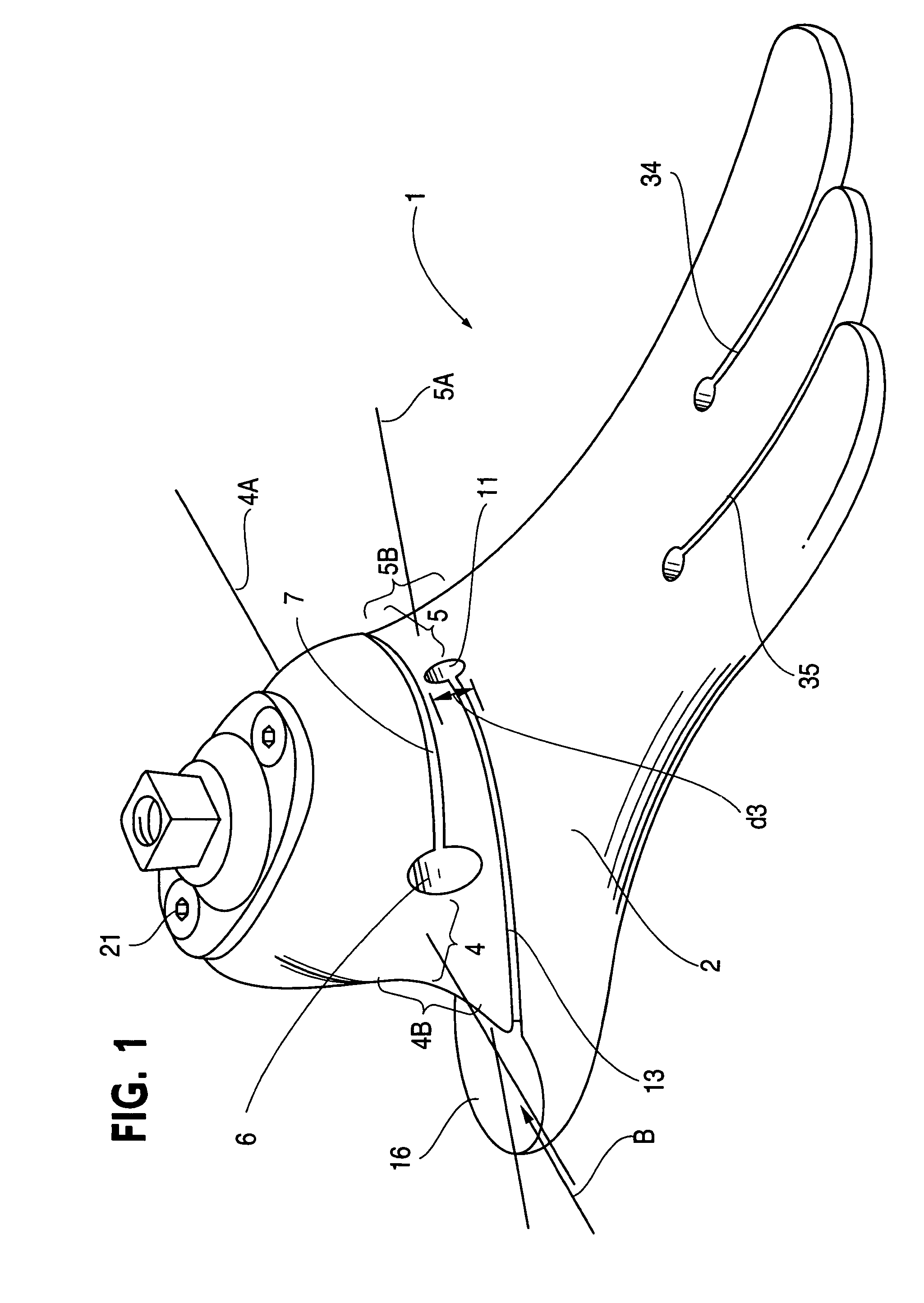
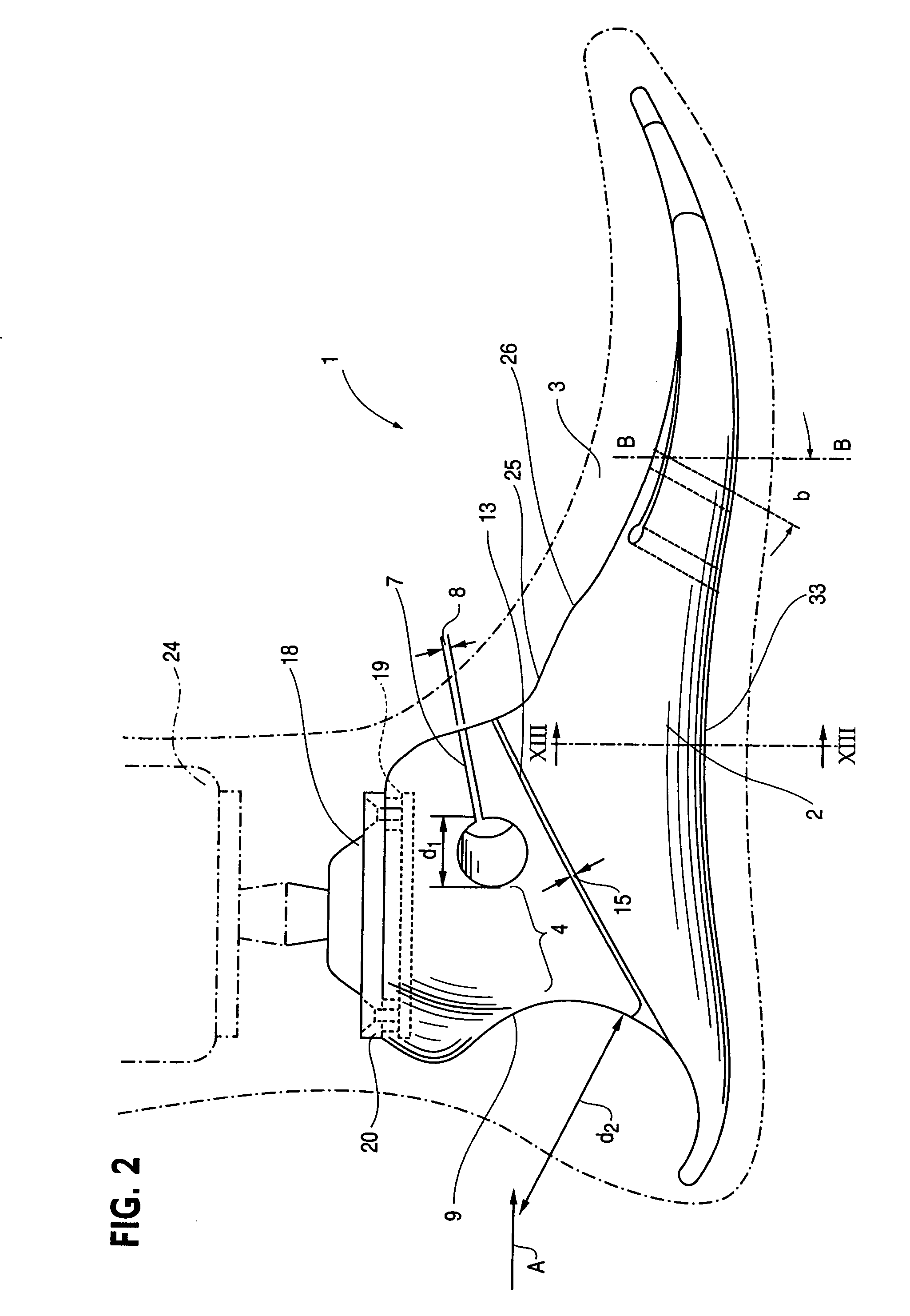
[0044]Referring now to the drawings, a prosthetic foot 1 of a first example embodiment of the invention comprises a body 2 formed of a resilient, semi-rigid material, plastic in the disclosed embodiment, which is formed with forefoot, midfoot and hindfoot portions 2A, 2B and 2C, respectively. A cosmetic covering 3 of the foot surrounds the body 2 as depicted in FIG. 2. The body 2 in the disclosed embodiment is formed by molding or by pouring the material of the body into a negative mold. However, other processes could be employed to form the body 2 such as machining the body from a solid piece of resilient, semi-rigid material, or by using a combination of molding and machining, for example. The plastic of body 2 is an elastomer, polyurethane in the illustrated example but other plastics or composite materials could be used. The body 2 of the foot is shaped and designed to simulate a human foot's hindfoot triplanar, forefoot biplanar and hindfoot, midfoot and forefoot dynamic respon...
PUM
Abstract
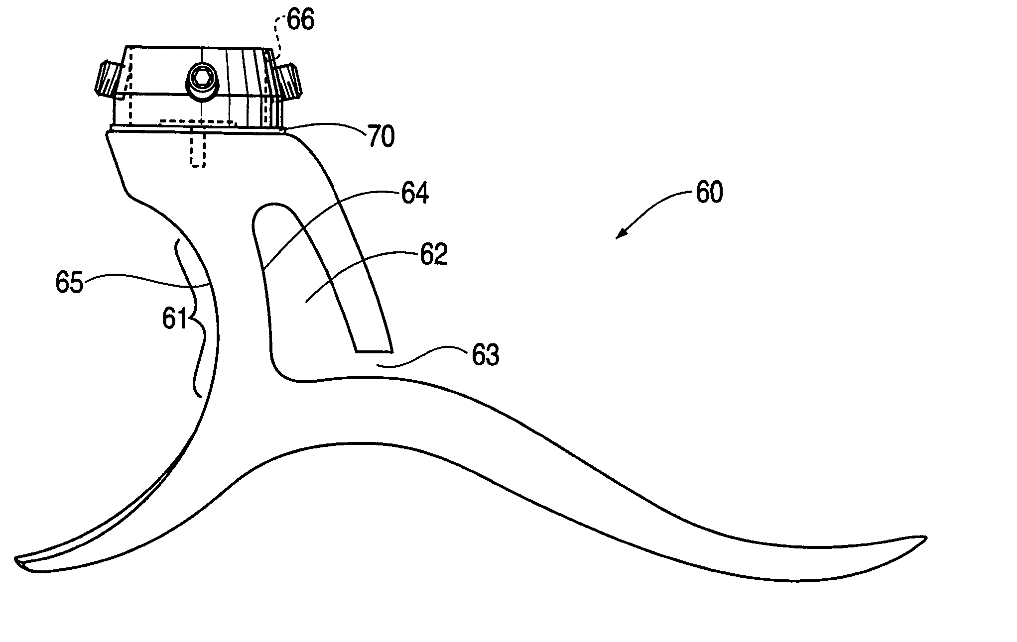
A prosthesis is disclosed for improving the gait and comfort qualities of the amputee that participates in walking, running and jumping activities. A foot and an ankle of the prosthesis are monolithically formed as a resilient member including a strut which forms an ankle joint. A hole extends through the resilient member with the periphery of the hole forming an anterior side surface of the strut. The resilient member anterior to the hole includes a gap to permit motion about the ankle joint axis while providing a stop in dorsiflexion. The hole is elongated upwardly such that the strut is upstanding and anterior convexly curved.
Description
RELATED APPLICATIONS[0001]This application is a continuation-in-part of application Ser. No. 10 / 790,177, filed Mar. 2, 2004, now U.S. Pat. No. 6,936,074 issued Aug. 30, 2005, which is a continuation of application Ser. No. 09 / 917,660, filed Jul. 31, 2001, now U.S. Pat. No. 6,743,260, issued Jun. 1, 2004, which is a continuation-in-part of application Ser. No. 09 / 742,077, filed Dec. 22, 2000, now U.S. Pat. No. 6,443,995, issued Sep. 3, 2002. This application is also a continuation-in-part of application Ser. Nos. 10 / 814,155 and 10 / 814,260, each filed Apr. 1, 2004, which are each:[0002]a continuation-in-part of application Ser. No. 10 / 473,682, which is the U.S. national designated filing under 35 U.S.C. §371 of international application PCT / US02 / 09589 filed Mar. 29, 2002, which is a continuation-in-part of U.S. application Ser. No. 09 / 820,895, filed Mar. 30, 2001, now U.S. Pat. No. 6,562,075 issued May 13, 2003; and[0003]a continuation-in-part of application Ser. No. 10 / 263,795 filed ...
Claims
Application Information
Patent Timeline
Application Date:The date an application was filed.
Publication Date:The date a patent or application was officially published.
First Publication Date:The earliest publication date of a patent with the same application number.
Issue Date:Publication date of the patent grant document.
PCT Entry Date:The Entry date of PCT National Phase.
Estimated Expiry Date:The statutory expiry date of a patent right according to the Patent Law, and it is the longest term of protection that the patent right can achieve without the termination of the patent right due to other reasons(Term extension factor has been taken into account ).
Invalid Date:Actual expiry date is based on effective date or publication date of legal transaction data of invalid patent.

