
Test head docking system and method

a test head and docking technology, applied in the field of test head docking, can solve the problems of large and expensive test head, test head size and weight increase, and test head size and weight increase, and achieve the effect of reducing the size and weight of the test head, and reducing the cost of testing

Inactive Publication Date: 2006-09-19
INTEST CORP
View PDF23 Cites 29 Cited by
  • Summary
  • Abstract
  • Description
  • Claims
  • Application Information

AI Technical Summary

Benefits of technology

[0120]In the above, the invention has been described in terms of a dock having circular cams. It will be apparent to those who are familiar with the art, that the same principles can be applied with equal advantage to docks having linear cams.

Problems solved by technology

The electronic testing itself is provided by a large and expensive ATE system which includes a test head which is required to connect to and dock with the handling apparatus.
The test head is extremely heavy, and as DUTs become increasingly complex with increasing numbers of electrical connections, the size and weight of test heads have grown from a few hundred pounds to presently as much as two or three thousand pounds.
Typically, the contact elements are spring loaded “pogo pins.” Overall, the contacts are very fragile and delicate, and they must be protected from damage.
As the operator is attempting to maneuver the test head into approximate alignment and into a position where it can be captured by the docking mechanism, he or she must overcome the resilience of the system, which can often be difficult in the case of very large and heavy test heads.
Also, if the operator releases the force applied to the test head before the docking mechanism is appropriately engaged, the resilience of the compliance mechanisms may cause the test head to move away from the dock.
However, the amount of force that can be generated by a vacuum device is limited to the atmospheric air pressure multiplied by the effective area.
Thus, such docks are limited in their application.
For this reason the aforementioned coarse alignment pins are used, which adds to the overall cost and complexity.
However, as test heads have become even larger and as the number of contacts has increased, a number of problems have become apparent.
First, the force required to engage the contacts increases as the number of contacts increases.
With test heads occupying a volume of a cubic yard or more it becomes increasingly difficult for the operators to observe all of the gussets and cams to determine when the test head is in a ready to dock and the ready to actuate positions.
Also due to the resiliency of the compliance mechanisms and cable in the test head manipulator, the bounce back effect has made it difficult to maintain the test head in the ready to actuate position while simultaneously initiating the actuation.
A further difficulty that arises from the increased amount of force to be overcome by the actuation mechanism is that the cam motion can become unsynchronized due to the stretching of the cable.
A similar problem of mechanism distortion is known in docks using solid links and bell cranks.

Method used


Image

  • Test head docking system and method
  • Test head docking system and method
  • Test head docking system and method

Examples


Embodiment Construction

[0064]The present invention is directed to improving the basic manual dock as described above. In particular, it is directed towards simplifying the docking of large, heavy test heads having hundreds or thousands of electrical contacts requiring actuation forces of hundreds or thousands of pounds. The present invention also provides the means to either partially or fully automate the process of docking between the ready to actuate and fully docked positions. The present invention also reduces the amount of cable or linkage stretch that arises in a docking apparatus where the docking forces are very high.

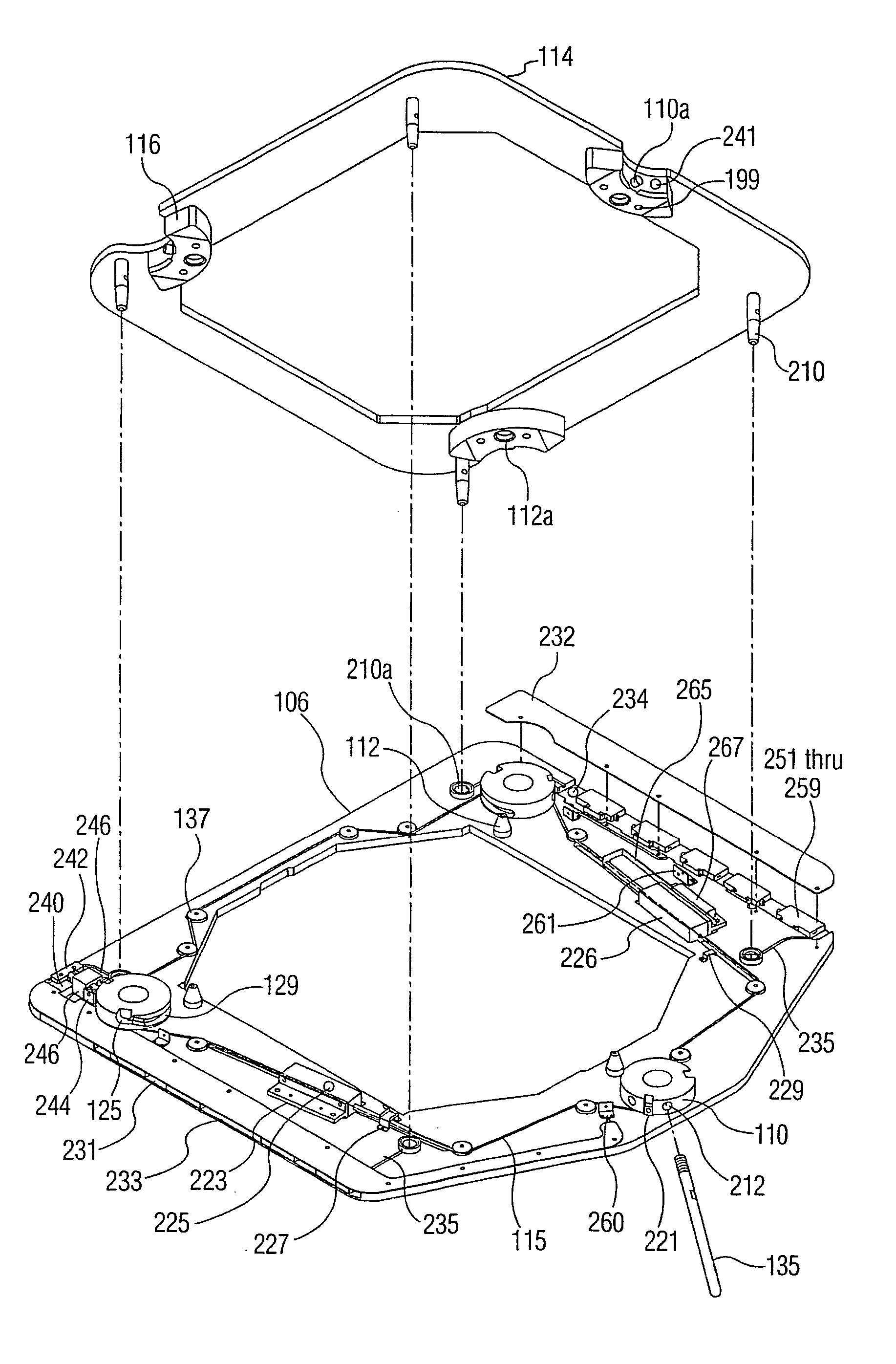
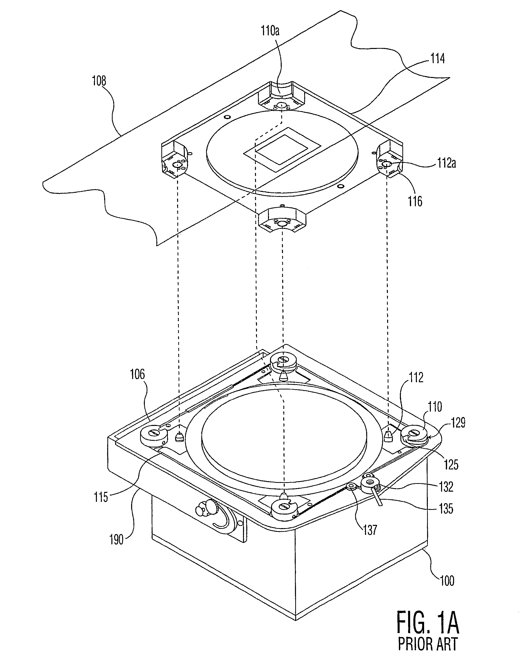
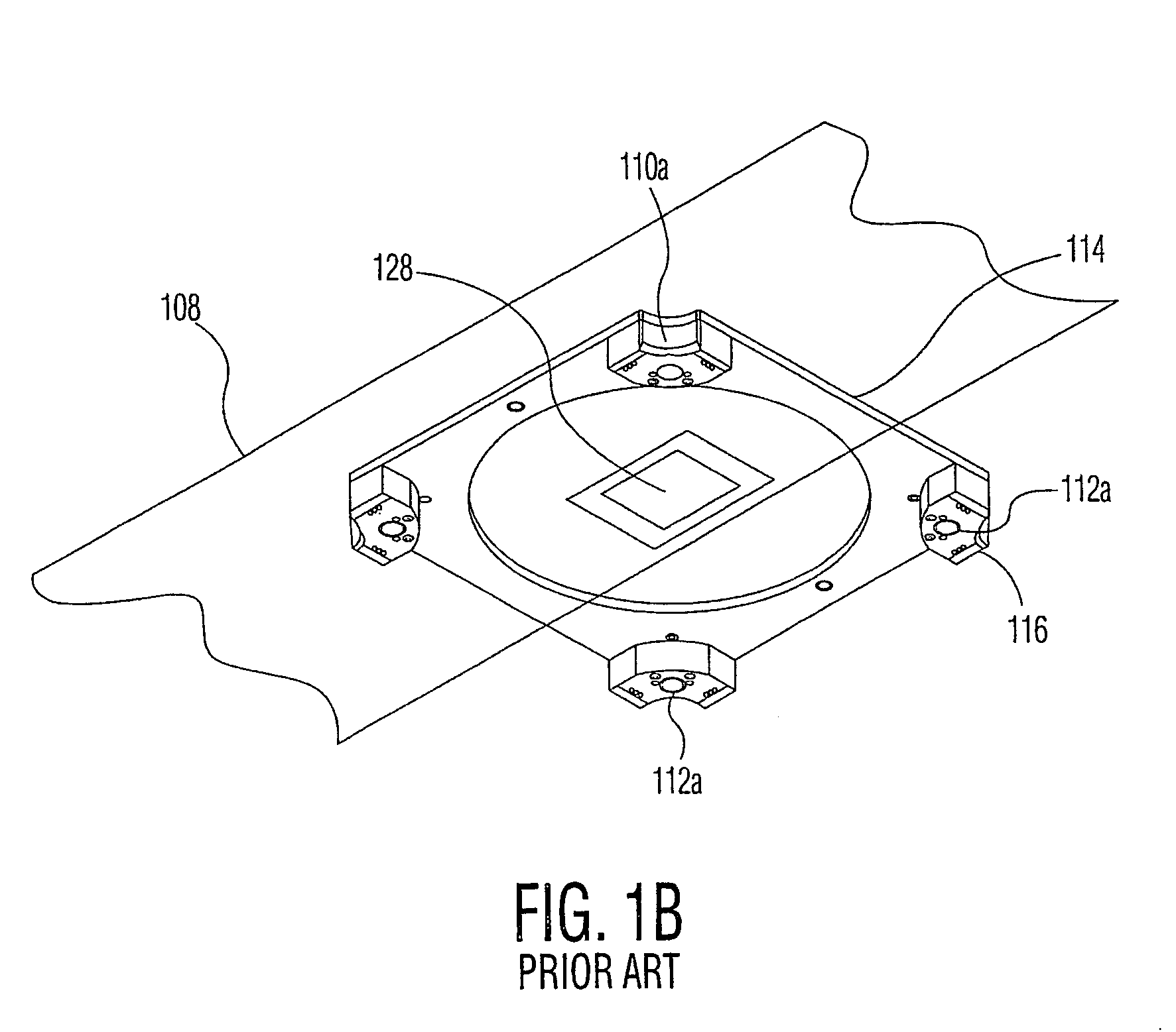
[0065]FIG. 2 is a perspective drawing of an improved dock in accordance with an exemplary embodiment of the present invention. FIG. 3A provides an enlarged view of the test head side of the docking apparatus illustrated in FIG. 2, and FIG. 3B provides an enlarged view of the handling apparatus side of the docking apparatus illustrated in FIG. 2. As in FIG. 1A, the docking apparatus i...


PUM


Abstract

A system for docking an electronic test head with a handling apparatus is provided. The system includes an assembly for at least partially aligning and subsequently bringing together the electronic test head and the handling apparatus. The system also includes a power driven actuator for providing only partially powered assistance in bringing together the electronic test head and the handling apparatus.

Description

[0001]THIS APPLICATION IS A U.S. NATIONAL PHASE APPLICATION OF PCT INTERNATIONAL APPLICATION PCT / US02 / 22193 WHICH CLAIMS PRIORITY BASED ON U.S. PROVISIONAL APPLICATION 60 / 305,633, FILED Jul. 16, 2001.FIELD OF THE INVENTION[0002]This invention relates to the field of electronic test head docking, and more specifically to a method and apparatus for test head docking using cams powered, at least partially, by one or more actuators for docking actuation.BACKGROUND OF THE INVENTION[0003]In the manufacture of integrated circuits (ICs) and other electronic devices, testing with automatic test equipment (ATE) is performed at one or more stages of the overall process. Special handling apparatus is used which places the device to be tested into position for testing. In some cases, the special handling apparatus may also bring the device to be tested to the proper temperature and / or maintain it at the proper temperature as it is being tested. The special handling apparatus is of various types ...

Claims


Application Information

Patent Timeline
Patent Type & Authority Patents(United States)
IPC IPC(8): G01R31/02G01R31/28H01L21/66
CPCG01R31/2887G01R31/2851G01R31/26H01L22/00
Inventor GUDIN, NAUMWEST, CHRISTOPHER L.WEILERSTEIN, I. MARVINNY, NILS O.HOLT, ALYN R.
Owner INTEST CORP
Learn More