Clamp pin for use by electrician or electrical lineworker

a technology for electricians and lineworkers, applied in the field of clamping pins, can solve the problems of not aligning the clamping pin with the clamping stick, the clamping stick is not useful in removing the clamping pin,

Inactive Publication Date: 2006-09-26
NORCROSS SAFETY PRODS
View PDF16 Cites 28 Cited by
  • Summary
  • Abstract
  • Description
  • Claims
  • Application Information

AI Technical Summary

Benefits of technology

[0012]Herein, the terms “upper” and “lower” are used to refer to ends of certain elements of the clamp pin in a useful orientation, in...

Problems solved by technology

Disadvantageously, however, the clamp stick is not useful in removing the clamp pin.
Disadvantageously, however, the ...

Method used


Image

  • Clamp pin for use by electrician or electrical lineworker
  • Clamp pin for use by electrician or electrical lineworker
  • Clamp pin for use by electrician or electrical lineworker

Examples


Embodiment Construction

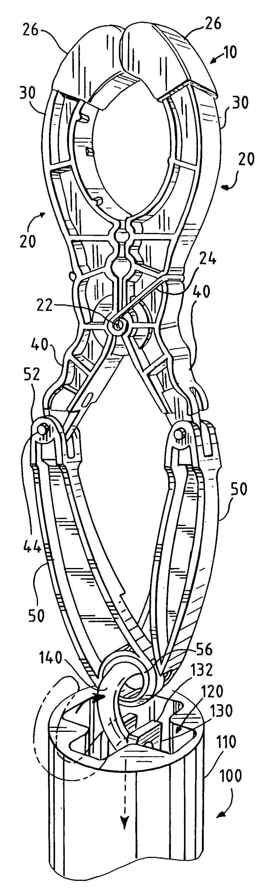
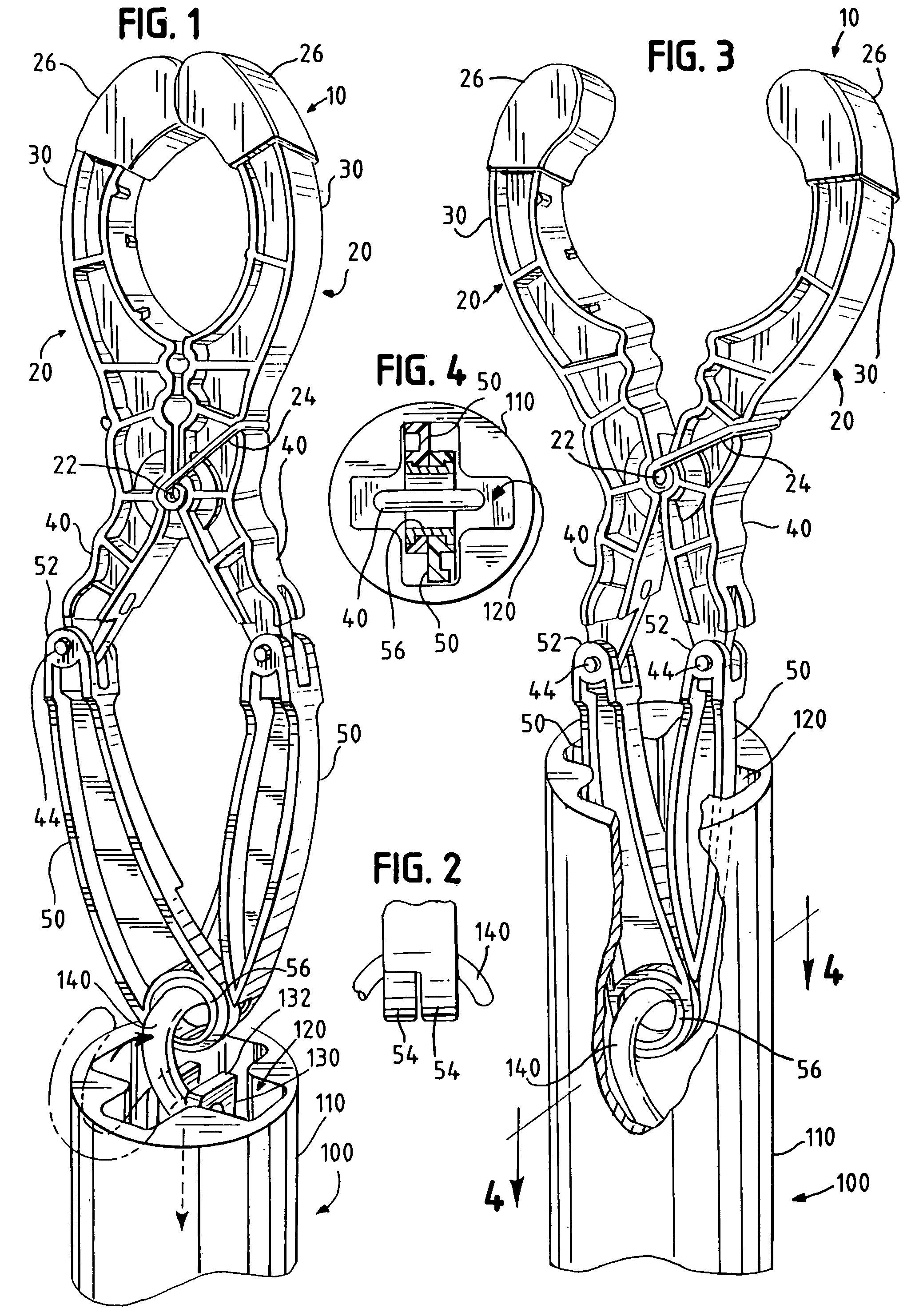
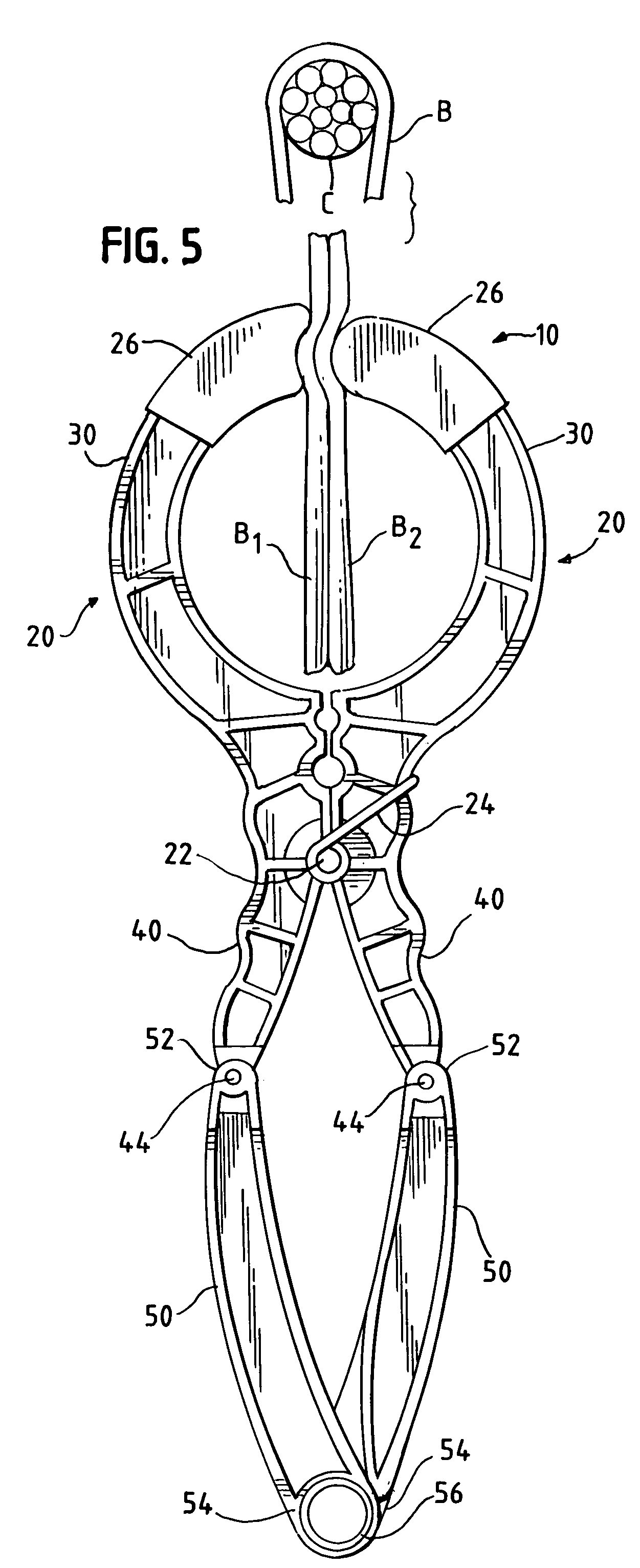
[0018]As illustrated in FIGS. 1 through 5, a clamp pin 10 embodying this invention is similar to clamp pins known heretofore in certain respects but differs from clamp pins known heretofore in other respects, which facilitate its use with a clamp stick 100 of the type noted above.

[0019]The clamp pin 10 is similar to clamp pins known heretofore in comprising two clamping jaws 20, each having a clamping arm 30 and an actuating arm 40. The clamping jaws 20 are connected pivotably to each other, via the core 22 of a torsion spring 24, between the clamping and actuating arms 30, 40. The clamping jaws 20 are configured so as to be thus pivotable between a closed condition, in which the clamping jaws 20 are illustrated in FIG. 1, and an opened condition, in which the clamping jaws 20 are illustrated in FIGS. 2 and 3. The clamping jaws 20 are biased, via the torsion spring 24, toward the closed condition. Each clamping jaw 20 has a rubber boot 26 covering the upper end of the clamping arm 3...


PUM


Abstract

A clamp pin has two clamping jaws, each having a clamping arm and an actuating arm. Being connected pivotably to each other between the clamping and actuating arms, the clamping jaws are pivotable between a condition in which the clamping arms are opened and a condition in which the clamping arms are closed and toward which the clamping jaws are biased. The clamp pin has two actuating links, each having a upper end, which is connected pivotably to the actuating arm of one of the clamping jaws, and each having a lower end. The actuating links are connected pivotably to each other at the lower ends, via a grommet. The clamp pin is useful and may be advantageously combined with a clamp stick having a socket and having a hook movable into and out from the socket, wherein the grommet is adapted to receive the hook and wherein the actuating links are adapted to be drawn into the socket, along with the hook, when the hook is received by the grommet.

Description

TECHNICAL FIELD OF THE INVENTION[0001]This invention pertains to a clamp pin of a type used by an electrician or an electrical lineworker to clamp an insulative blanket around a live electrical conductor or another electrical hazard. The clamp pin is used with a clamp stick of a type used by an electrician or an electrical lineworker for diverse tasks.BACKGROUND OF THE INVENTION[0002]As known heretofore and available commercially from Salisbury of Skokie, Ill., and from other sources, a clamp pin of the type noted above is made except for small parts, such as a torsion spring, from a dielectric material, either a hardwood or a suitable polymer, such as fiberglass-reinforced nylon. Such a pin has two clamping jaws, each of which has a clamping end and an actuating arm, which are connected pivotably to each other, which are pivotable between an opened condition and a closed condition, and which are biased toward the closed condition.[0003]In the opened condition, the clamping ends are...

Claims


Application Information

Patent Timeline
IPC IPC(8): B25B23/16B25B7/12
CPCB25B5/06B25B9/00B25B7/12H01R11/14
Inventor FLOJO, ALFRED R.
Owner NORCROSS SAFETY PRODS
Why Eureka
Try Eureka