Machine guarding system having a sensing mat with status indicator lights

a technology of status indicator lights and machine guarding, which is applied in the direction of insulated conductors, cables, instruments, etc., can solve the problems of difficult for persons approaching such a danger zone to ascertain the current status within the danger zone, and the person having a need to enter the danger zone may not be able to easily determine i

Active Publication Date: 2006-10-10
TAPESWITCH OF AMERICA
View PDF12 Cites 21 Cited by
  • Summary
  • Abstract
  • Description
  • Claims
  • Application Information

AI Technical Summary

Benefits of technology

[0017]As a result of the present invention, a safety system is provided to visually indicate an interactive status between persons and machines, equipment and other dangerous devices. Status indicator lights incorporated in a sensing mat of the safety system serve to indicate, enhance or draw attention to the current status of a potential danger zone surrounding a machine or other industrial equipment.

Problems solved by technology

Such dangerous equipment includes welding machines, robotic assembly devices, metal cutting equipment and the like, all of which may be self-operating or person-operated.
Similarly, anyone entering the danger zone will step on the switch mat to terminate power to the dangerous equipment.
While such switch mat based safety systems are effective in terminating power to a piece of dangerous equipment upon a change in status within the danger zone, it is often difficult for persons approaching such a danger zone to ascertain the present status within the danger zone.
In particular, a person having a need to enter the danger zone may not be able to easily determine if it is indeed safe to enter (e.g., the dangerous machinery is already turned off), or whether the zone is in a danger status (e.g. the machinery is operating).

Method used


Image

  • Machine guarding system having a sensing mat with status indicator lights
  • Machine guarding system having a sensing mat with status indicator lights
  • Machine guarding system having a sensing mat with status indicator lights

Examples


Embodiment Construction

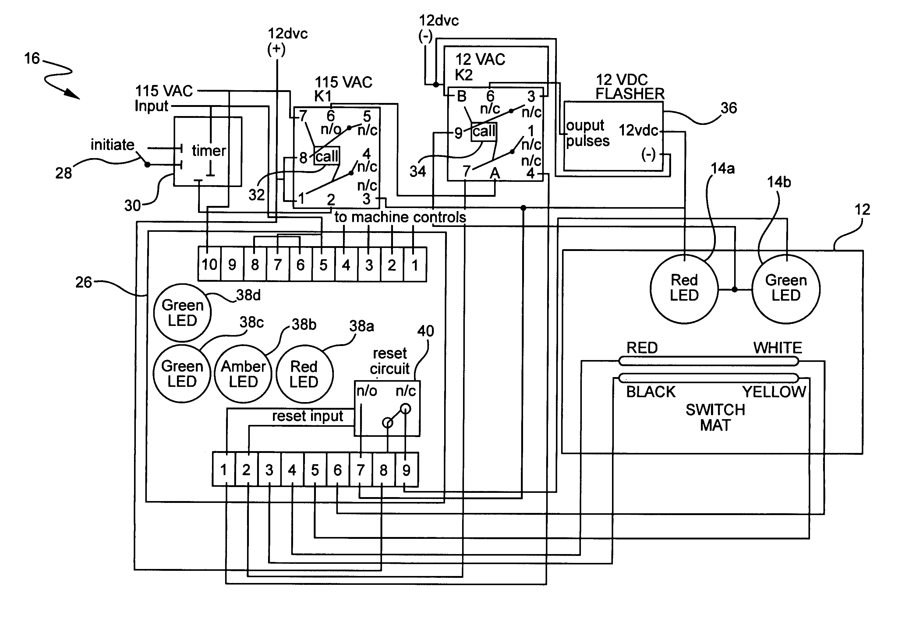
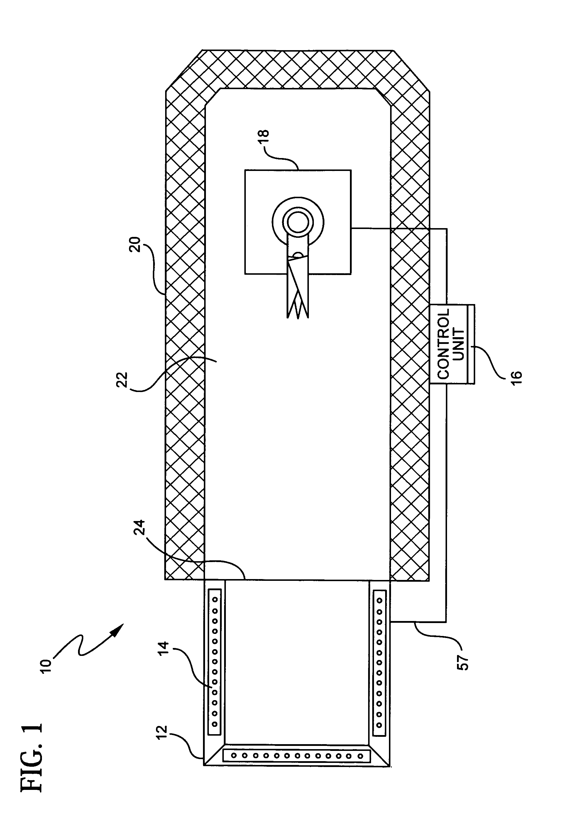
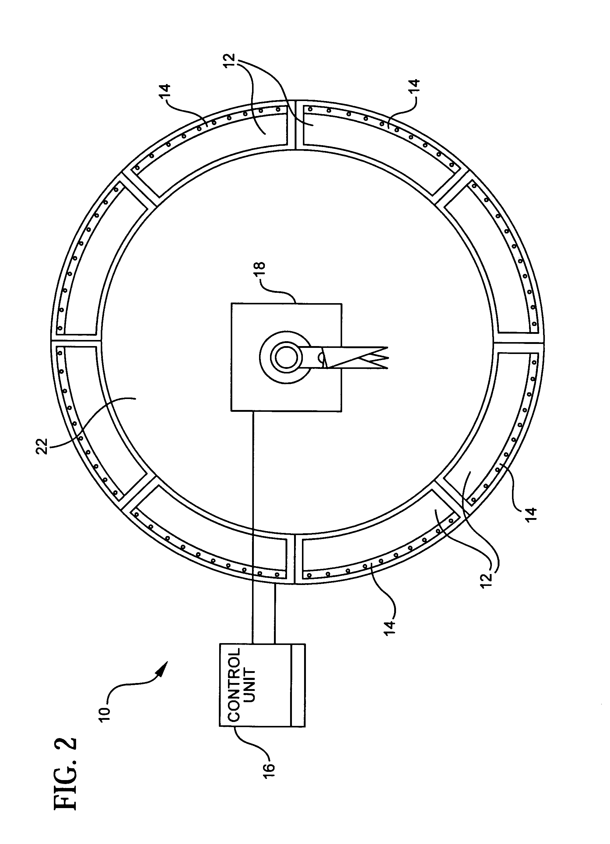
[0024]Referring first to FIG. 1, a machine guarding system 10 formed in accordance with the present invention generally includes an electrical switch mat 12 having status indicator lights 14 incorporated therein and a control unit 16 electrically connected to the switch mat. A switch mat or sensing mat as used herein is also defined as encompassing sensing edges, sensing bumpers and ribbon switches.

[0025]The control unit 16 is electrically connected to a machine 18 or other piece of dangerous equipment for controlling power to the machine based on activation of the switch mat 12. The guarding system arrangement shown in FIG. 1 includes a hard guarding cage 20 substantially surrounding the machine 18 to define a danger zone 22 having an entrance 24. In this arrangement, the switch mat 12 is located at the entrance 24 to the danger zone 22 so that anyone entering the danger zone will necessarily step on the switch mat.

[0026]As described above, however, a plurality of switch mats 12 ma...


PUM


Abstract

A machine guarding system generally includes a switch mat in electrical communication with a machine being guarded. The switch mat is adapted to be placed on a floor adjacent the machine being guarded and includes a pressure actuated switch mechanism which causes power to the machine to be terminated when a pressure is applied to the switch mat. The switch mat further includes a status indicator display disposed on a surface of the switch mat which is illuminated based on a status of the machine being guarded. In a preferred embodiment, the machine guarding system further includes a machine control unit for controlling power to the machine being guarded. The switch mat is in electrical communication with the machine control unit, wherein the switch mechanism causes the machine control unit to terminate power to the machine when a pressure is applied to the switch mat. The machine control unit also illuminates the indicator display based on a status of the machine being guarded.

Description

BACKGROUND OF THE INVENTION[0001]The present invention relates generally to safety systems to protect persons from injury from industrial machines, and more particularly, to a system for terminating power and indicating an active condition of a machine.[0002]It is known in the art to provide safety systems for dangerous machinery and industrial apparatus to protect persons from injury from such equipment. Such dangerous equipment includes welding machines, robotic assembly devices, metal cutting equipment and the like, all of which may be self-operating or person-operated. Generally, safety systems for such machinery typically involve some form of means for preventing personnel from inadvertently approaching the dangerous equipment or involve some form of alarm or power cut-off to the machine which is activated upon a dangerous condition, such as when a person gets too close to the dangerous equipment. Examples of such safety systems include dual hand operated controls which forces ...

Claims


Application Information

Patent Timeline
Patent Type & Authority Patents(United States)
IPC IPC(8): G08B21/00
CPCF16P3/14H01H3/141F16P3/144F16P3/12H01H9/182
Inventor GRZAN, JOHNKEATS, ROBERT
Owner TAPESWITCH OF AMERICA
Why Eureka
Try Eureka