
Multi-band antenna

a multi-band antenna and antenna technology, applied in the direction of resonant antennas, elongated active element feeds, radiating element structural forms, etc., can solve the problems of restrainting the application of antennas in other frequency bands of 5.75, 5.825 ghz, etc., and achieve the effect of wide bandwidth

Inactive Publication Date: 2006-10-10
HON HAI PRECISION IND CO LTD
View PDF5 Cites 125 Cited by
  • Summary
  • Abstract
  • Description
  • Claims
  • Application Information

AI Technical Summary

Problems solved by technology

However, the antenna cannot be used in another frequency band of 5.75–5.825 GHz which is also under IEEE 802.11a standard.
Moreover, the lower and the higher frequency bands of the antenna are narrow, which restrains the application of the antenna.

Method used


Image

  • Multi-band antenna
  • Multi-band antenna
  • Multi-band antenna

Examples


Embodiment Construction

[0019]Reference will now be made in detail to a preferred embodiment of the present invention.

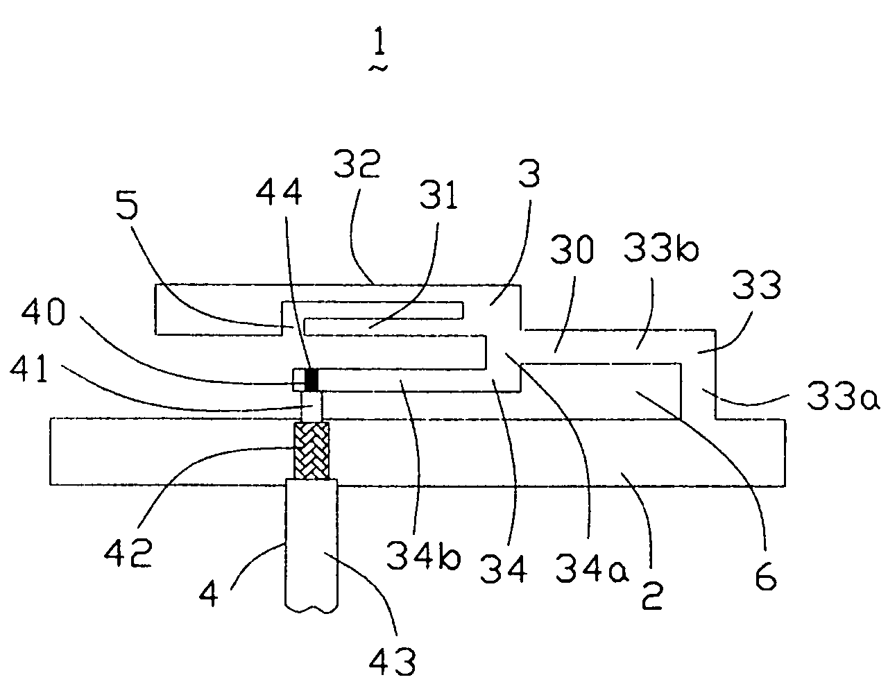
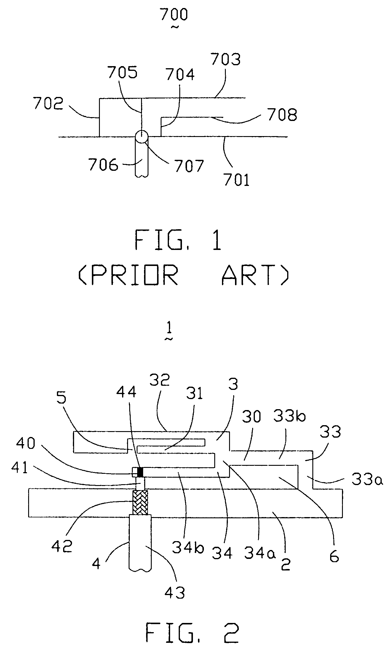
[0020]A multi-band antenna 1 according to the present invention is used in an electronic device for transmitting and receiving electromagnetic signals. In this preferred embodiment, the electronic device is a laptop computer (not shown). The antenna 1 is integrally made up of a metallic sheet via setting slots therein. Said metal sheet can be a bracket, which is settled between a LCD and a cover of the laptop computer, or a frame for supporting and protecting the LCD, or a shielding (not shown) at the back of the LCD for preventing an Electro Magnetic Interference (EMI) of other electronic components (not shown), or other possible positions in the electronic device.

[0021]Referring to FIG. 2, the multi-band antenna 1 comprises a ground portion 2, a radiating portion 3 and a coaxial transmission line 4.

[0022]The radiating portion 3 comprises a first radiating portion 30, a second radiating po...


PUM


Abstract

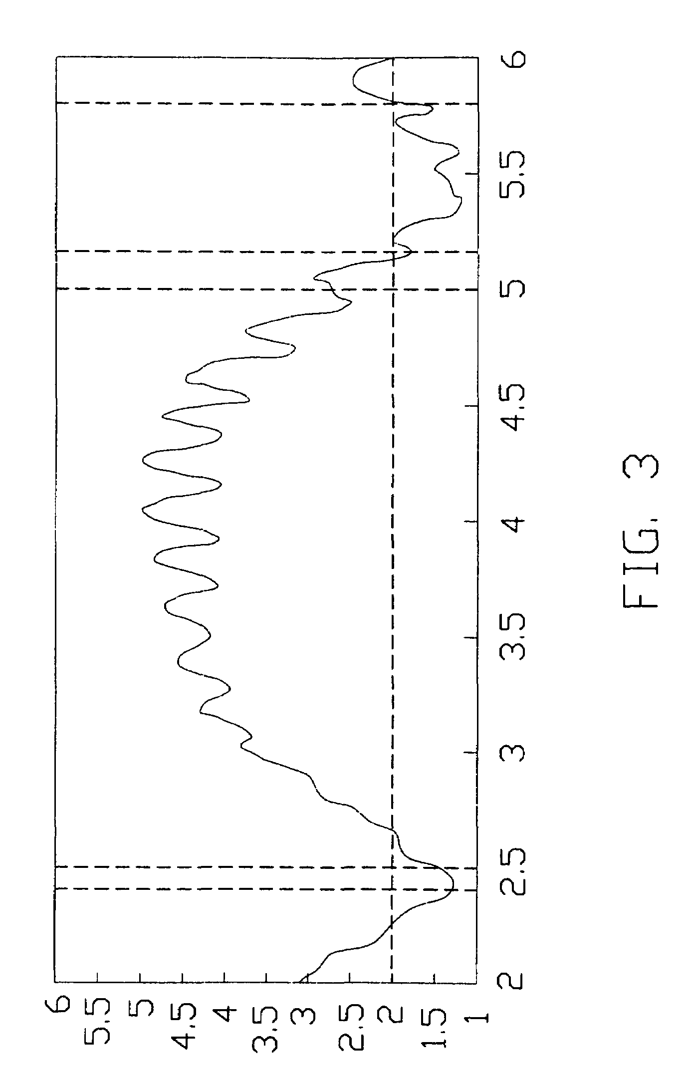
A multi-band antenna (1) used in an electronic device and formed of a metallic sheet by defining holes therein, including a first radiating portion (30), a second radiating portion (31), a third radiating portion (32), a ground portion (2), and a coaxial transmission line (4). The first radiating portion, the ground portion and the coaxial transmission line cooperatively form a loop antenna operated at a higher frequency band of about 5.15–5.875 GHz. The second radiating portion, the ground portion and the coaxial transmission line cooperatively form a first inverted-F antenna operated at another higher frequency band of about 5.725–5.875 GHz. The third radiating portion, the ground portion and the coaxial transmission line cooperatively form a second inverted-F antenna operated at a lower frequency band of about 2.4–2.5 GHz.

Description

BACKGROUND OF THE INVENTION[0001]1. Field of the Invention[0002]The present invention relates generally to an antenna, and more particularly to a multi-band antenna for use with an electronic device.[0003]2. Description of the Prior Art[0004]The prosperous development of wireless communication industry brings various products and techniques for multi-band communication such that many new products have the performance for wireless communication so as to meet the consumers' demand. Such products as WLAN cards with antennas on / in them for use with a laptop computer or a personal digital assistance (PDA) are gaining popularity in wireless communication market. These cards benefit from multi-band antennas operated under IEEE 802.11a / b / g standard. In most cases, embedded multi-band antennas are arranged in an electronic device directly, rather than via a WLAN card. Whatever, a multi-band antenna with small size and high performance is essential and critical to achieve the purpose for wire...

Claims


Application Information

Patent Timeline
Patent Type & Authority Patents(United States)
IPC IPC(8): H01Q1/24H01Q5/00H01Q5/371H01Q9/20H01Q9/42H01Q21/30
CPCH01Q9/42H01Q5/371H01Q21/30
Inventor LIN, HSIEN CHUTAI, LUNG SHENGHUNG, CHEN-TA
Owner HON HAI PRECISION IND CO LTD
Learn More