Method and apparatus for a dual power supply to embedded non-volatile memory

a non-volatile memory and power supply technology, applied in static storage, digital storage, instruments, etc., can solve the problems of time and current consumption of boosting, and achieve the effect of avoiding internal boosting delays and avoiding over-sizing of write charge pumps

Active Publication Date: 2006-10-10
SONRAI MEMORY LTD
View PDF16 Cites 69 Cited by
  • Summary
  • Abstract
  • Description
  • Claims
  • Application Information

AI Technical Summary

Benefits of technology

[0009]The invention consists of a dual power supply memory management system that provides an external voltage level to memory as well as the internally generated voltage level. The low voltage, logic parts of the memory may use thin oxide devices and are supplied by the regulated voltage level, while the external voltage level is directly supplied to the charge pump for memory write, and to the word line and bit line decoding during memory read. The invention allows for high-speed devices for decoding and sensing, while avoiding internal boosting delays during memory read, and avoiding over-sizing of the write charge pump.

Problems solved by technology

However, using regulated voltage level 30 during memory write and read for memory 40 results in several issues.
However, boosting is time and current consuming.
However, the logic parts of memory 240 typically use thick oxide devices, because thin oxide devices do not operate at external voltage level 210.

Method used


Image

  • Method and apparatus for a dual power supply to embedded non-volatile memory
  • Method and apparatus for a dual power supply to embedded non-volatile memory
  • Method and apparatus for a dual power supply to embedded non-volatile memory

Examples


Embodiment Construction

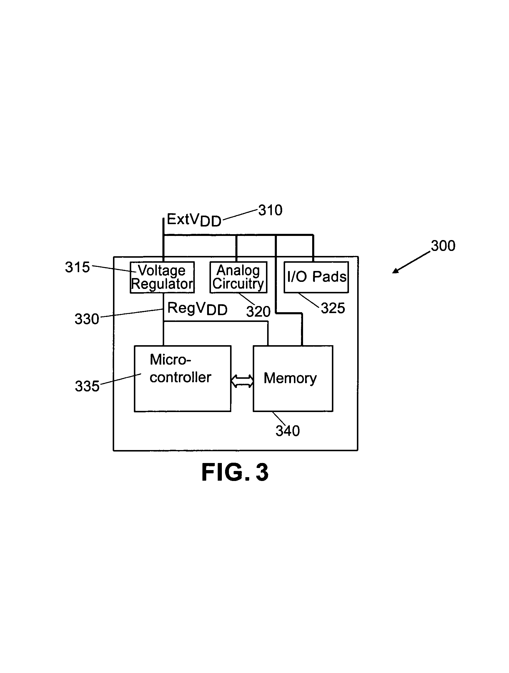
[0021]FIG. 3 is a schematic illustrating one embodiment of a power supply management system for memory in a system-on-a-chip (SOC). SOC 300 illustrates one example of how power is distributed. External voltage level 310, for example 3.3V or 5V, is applied to voltage regulator 315, analog circuit 320, and input / output pads 325. Voltage regulator 315 generates regulated voltage level 330, for example 1.8V for a 0.18 μm logic. Regulated voltage level 330 is applied to memory 340, for example embedded EEPROM and FLASH memory, and advanced logic 335, for example the micro-controller, CMOS memories, glue logic etc. External voltage level 310 is also applied to memory 340.

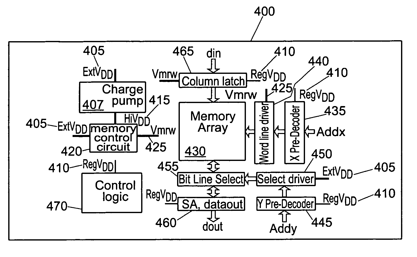
[0022]FIG. 4 is a schematic diagram illustrating one embodiment of memory 340 from FIG. 3. Memory 400 receives external voltage level 405 and regulated voltage level 410 (from voltage regulator 315 of FIG. 3). Charge pump 407 receives external voltage level 405 and generates high voltage level 415, which is used to progra...


PUM


Abstract

A charge pump is configured to receive an external voltage level and generate a high voltage level, wherein the high voltage level is higher than the external voltage level. A memory control circuit is configured to receive the external voltage level and the high voltage level, and to select one of the voltage levels. A memory array, with a word line and a bit line, is configured to receive the external and high voltage levels at the word line and the high voltage levels at the bit line. A word line driver is configured to provide the external and high voltage levels to the word line. A bit line selector is configured to select the bit line and receive the high, external, and regulated voltage levels. A bit line driver is configured to provide the external voltage levels to the bit line selector.

Description

CROSS REFERENCE TO RELATED APPLICATIONS[0001]This application claims priority to French Patent Application Serial Number 04 03434, filed Apr. 1, 2004, the entirety of which is incorporated herein.BACKGROUND OF THE INVENTION[0002]The invention relates generally to managing voltage differences between shrinking transistor technology and non-volatile memory read / write requirements. Specifically, the invention relates to power supply management for embedded non-volatile memory such as electrically erasable programmable read-only memory (EEPROM) and FLASH memory.DESCRIPTION OF THE RELATED ART[0003]In order to maintain acceptable power consumption and reliability with advanced technology, supply voltage has been reduced from 5V with 1 μm technology down to 1.8V with 0.18 μm technology. However, supply voltage has not decreased at the system level. Most systems on chips (SOCs) using a 0.18 μm technology are 3.3V compliant, and 5V compliant or tolerant.[0004]FIG. 1 is a schematic illustrati...

Claims


Application Information

Patent Timeline
Patent Type & Authority Patents(United States)
IPC IPC(8): G11C16/08G11C16/02G11C5/14G11C7/12G11C8/08G11C16/12G11C16/30
CPCG11C7/12G11C8/08G11C16/12G11C16/30G11C5/14
Inventor DAGA, JEAN-MICHEL
Owner SONRAI MEMORY LTD
Why Eureka
Try Eureka