Reduction of linear birefringence in circular-cored single-mode fiber

a single-mode fiber and linear birefringence technology, applied in the field of fiber optics, can solve the problems of reducing the efficiency of fiber or coil fabrication process, affecting the quality of fiber, and reducing so as to reduce the effect of linear birefringence and reduce linear birefringen

Inactive Publication Date: 2006-10-10
KVH IND INC
View PDF112 Cites 7 Cited by
  • Summary
  • Abstract
  • Description
  • Claims
  • Application Information

AI Technical Summary

Benefits of technology

[0008]The invention relates to reducing the effect of linear birefringence in an optical fiber, in particular a circular-cored single-mode fiber. According to one aspect of the invention, a method is disclosed of reducing linear birefringence in an optical fiber, which may include subdividing a length of the optical fiber into a plurality of sections, and introducing between the sections a twist having a predetermined sense of rotation and a twist angle. Twist, as used herein, may be a permanent rotational displacement of the fiber from its initial position over a distance which is a small fraction of a beat length. In one method, the twist occurs over a length of les...

Problems solved by technology

As this effect is temperature dependent, and each fiber has different characteristics, it is difficult to produce a sensing coil whose characteristics are known over the operating temperature...

Method used


Image

  • Reduction of linear birefringence in circular-cored single-mode fiber
  • Reduction of linear birefringence in circular-cored single-mode fiber

Examples


first embodiment

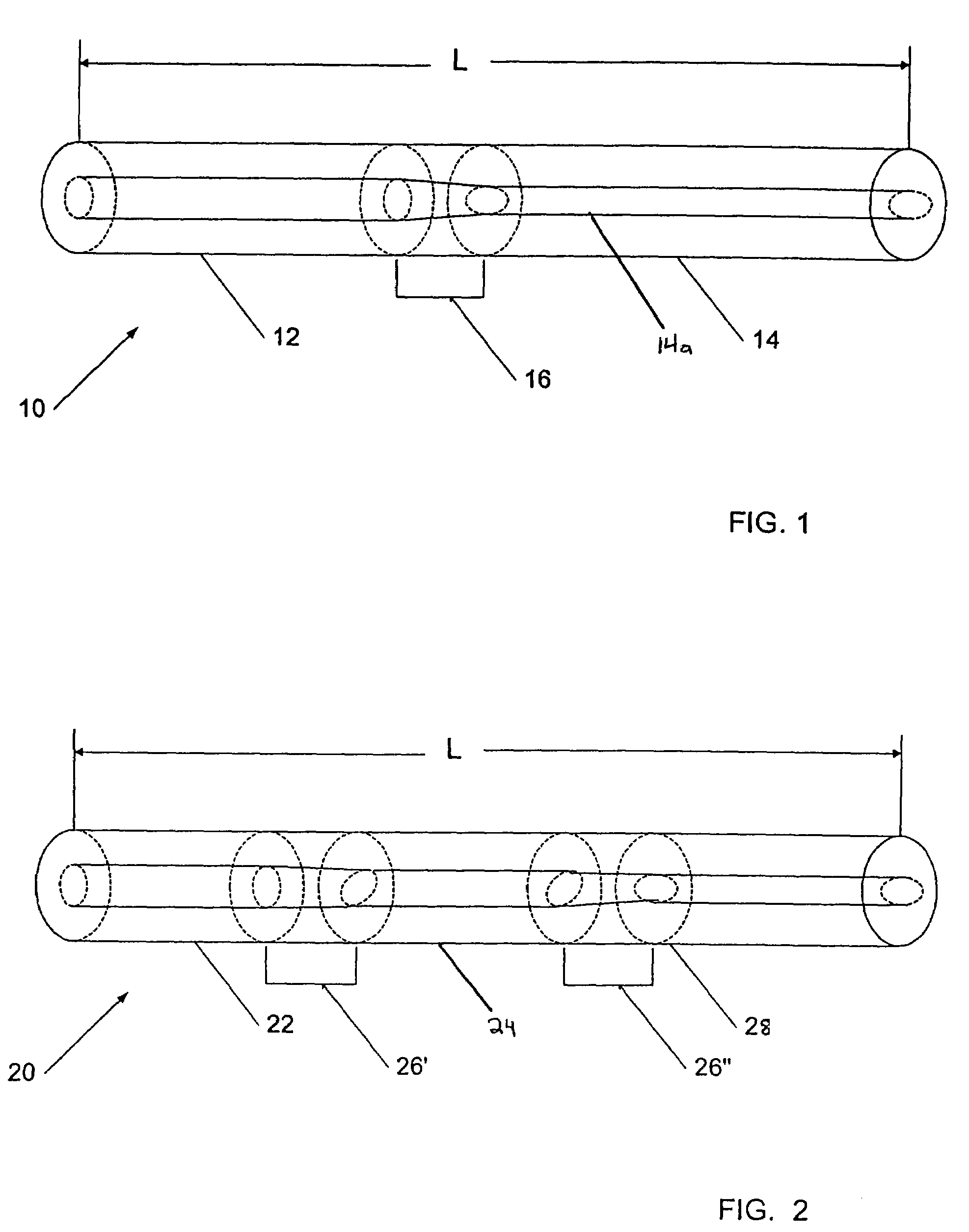
[0022]Referring now to FIG. 1, in the invention, a length L of an optical fiber 10 may be segmented into two sections 12 and 14, with an approximate 90° splice or twist 16 introduced between the sections 12 and 14. The individual sections 12, 14 may run straight and may not include twists. The light waves propagate in the fiber 10 across both sections 12 and 14 without changing their physical general orientation, but the axis x—x of the fiber ellipse 12a of fiber section 12 will rotate by approximately 90° at the splice 16 to axis x′—x′ of fiber ellipse 14a of section 14. This may have the effect of interchanging the effects of the linear birefringence between the two orthogonal waves. By the time that the two waves introduced at one end of the fiber section 12 reach the far end of the second fiber section 14, the overall retardation may be the same for each mode for the case having even numbers of fiber sections, such as the two sections of FIG. 1. This may have the effect of elimi...

second embodiment

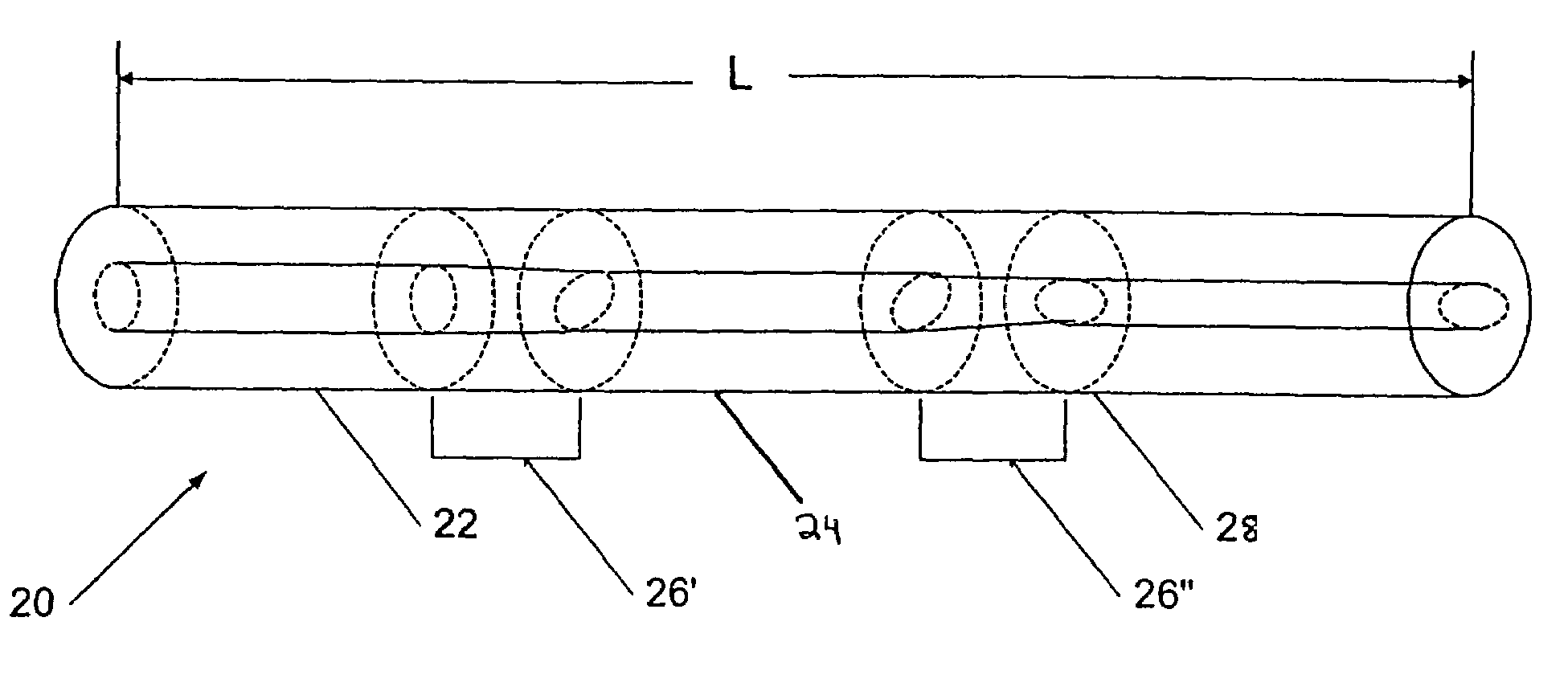
[0025]FIG. 2 depicts a second embodiment using a lesser angle, for example, 45°. In this embodiment, a length L of an optical fiber 20 may be segmented into several sections. The illustrated example depicts three sections 22, 24, and 28, with two 45° splices or twists 26′, 26″ introduced along the fiber length. Successive twists would preferably continue in the same sense of rotation, until the total accumulated twist angle is approximately 90°. Thereafter, the sense of rotation may be reversed. The individual light waves will continue to propagate in the fiber 20 across the three sections 22, 24 and 28 without changing their physical orientation, but the axis y-y of the fiber ellipse 22a of section 22 will rotate by approximately 90° after traversing both splices 26′, 26″ to axis y′—y′ of the fiber ellipse 28a of section 28.

[0026]If this occurs often enough, it may minimize the effects of linear birefringence and may stabilize the fiber sensitivity to the Faraday effect. In the emb...


PUM


Abstract

A method is described for reducing the effect of linear birefringence in an optical fiber, in particular a circular-cored single-mode fiber. The invention may also be directed to an optical fiber having a reduced linear birefringence. A length of the optical fiber may be subdivided into a plurality of sections and a twist having a predetermined sense of rotation and a twist angle may be introduced between the sections. Fibers of this type may find applications, for example, in fiber-optic current and magnetic field sensors.

Description

RELATED APPLICATIONS[0001]This application claims priority to, and incorporates by reference, the entire disclosure of U.S. Provisional Patent Application No. 60 / 222,389, filed on Aug. 2, 2000.FIELD OF THE INVENTION[0002]The invention relates to the field of fiber optics, and more particularly to birefringence in single-mode fibers.BACKGROUND OF THE INVENTION[0003]Linear birefringence in a single-mode fiber optic sensing coil employing the Faraday effect has the effect of reducing the sensitivity of the coil to magnetic fields. The sensitivity decreases with increasing length and birefringence of the coil. Birefringence occurs even if the sensing fiber is straight, due to the presence of residual linear birefringence resulting from core ellipticity. Even nominally circular core single mode fibers possess some core ellipticity due to imperfections in the production process. Additionally, bending or other anisotropic stresses on the core contribute to birefringence, such as when the f...

Claims


Application Information

Patent Timeline
IPC IPC(8): G02B6/00G02B6/10G02B6/38
CPCG02B6/105G02B6/3833
Inventor DYOTT, RICHARDBENNETT, SID
Owner KVH IND INC
Why Eureka
Try Eureka