
An all-fiber pulsed current sensor

A pulse current and sensor technology, applied in the direction of voltage/current isolation, measuring current/voltage, instruments, etc., can solve the problems of low measurement accuracy and small measurement range of optical fiber current sensors, and achieve improved measurement accuracy, low phase delay coefficient, The effect of reducing the impact

Inactive Publication Date: 2011-11-30
INST OF FLUID PHYSICS CHINA ACAD OF ENG PHYSICS
View PDF0 Cites 7 Cited by
  • Summary
  • Abstract
  • Description
  • Claims
  • Application Information

AI Technical Summary

Problems solved by technology

[0004] In order to solve the shortcomings of small measurement range and low measurement accuracy of optical fiber current sensors in the prior art, the present invention provides an all-fiber pulse current sensor

Method used


Image

  • An all-fiber pulsed current sensor
  • An all-fiber pulsed current sensor

Examples


Embodiment Construction

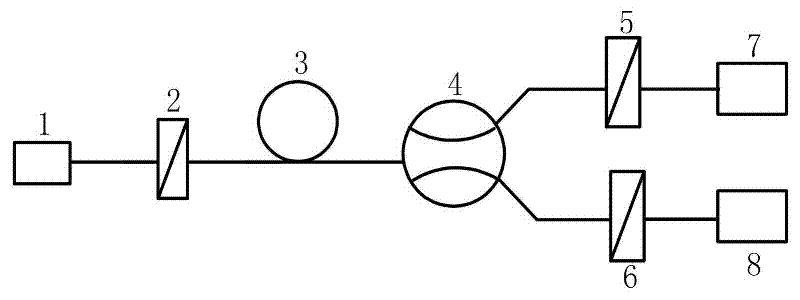
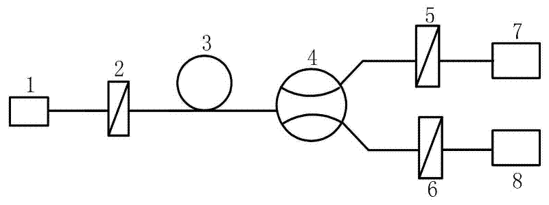
[0010] The present invention will be described in further detail below in conjunction with the accompanying drawings.

[0011] The all-fiber pulse current sensor of the present invention comprises DFB laser 1, online fiber polarizer 2, low birefringence single-mode fiber 3, 1×2 polarization-maintaining fiber coupler 4, on-line fiber analyzer I5, on-line Optical fiber analyzer II6, PIN photodetector I7 and PIN photodetector II8. The connection relationship is that the DFB laser 1 is connected to the online fiber polarizer 2 and the low birefringence single-mode fiber 3 in sequence, and the low birefringence single-mode fiber 3 is connected to an interface of the input end of the 1×2 polarization-maintaining fiber coupler 4 (The other interface is idle), one interface of the output end of the 1×2 polarization-maintaining fiber coupler 4 is connected to the on-line fiber optic polarizer I5 and the PIN photodetector I7 in sequence; the other interface is connected to the on-line f...


PUM


Abstract

The invention discloses an all-optical fiber current sensor suitable for pulse current measurement. The beam radiated by the DFB laser becomes linearly polarized light after passing through the online fiber polarizer, and enters the low birefringence single-mode fiber, and its polarization state is modulated by the magnetic field generated by the pulse current to be measured. The beam emitted from the low-birefringence single-mode fiber enters the 1×2 polarization-maintaining fiber coupler and is split into two output beams with the same polarization state as the input beam. Two online fiber optic polarizers are connected to the two output ports of the 1×2 polarization-maintaining fiber coupler, one of which has the same polarization direction as the online fiber polarizer, and the other has a 45° included angle with it. The beams emitted from the two online fiber optic analyzers enter two PIN photodetectors and are converted into electrical signals. The pulse current to be measured can be obtained by processing the two electrical signals with a phase difference of 90°. The all-fiber pulse current sensor of the invention has the advantages of high measurement accuracy and wide measurement range.

Description

technical field [0001] The invention belongs to the technical field of optical fiber sensor measurement, and in particular relates to a sensor for measuring pulse current by using the Faraday magneto-optic effect. Background technique [0002] High-power pulse technology, accelerator technology, high-energy-density physics and other fields and fault diagnosis of high-voltage transmission lines in the power industry need to accurately measure pulse currents with amplitudes as high as hundreds of kA, or even MA levels. Rogowski coils and B-dot probes are often used at present. Needle measurement pulse current, but because of its poor anti-electromagnetic interference ability, weak ability to withstand high voltage, it is difficult to use in some specific occasions. [0003] The all-fiber current sensor is an active sensor developed by using the Faraday magneto-optic effect. It has the advantages of anti-strong electromagnetic interference, high voltage resistance, small size ...

Claims


Application Information

Patent Timeline
Patent Type & Authority Applications(China)
IPC IPC(8): G01R19/00G01R15/24
Inventor 邓向阳李泽仁彭其先陈光华蒙建华王德田
Owner INST OF FLUID PHYSICS CHINA ACAD OF ENG PHYSICS
Learn More