Method and device for high-accuracy and small-angle measurement

A measurement method and small-angle technology, applied in the field of optical measurement, can solve problems such as the decrease of the measurement range, the difficulty of installing and adjusting the sensing system, and the difficulty of overcoming the influence of the measurement accuracy of the measurement reference, etc., and achieve simple structure, large measurement range, and small volume Effect

Inactive Publication Date: 2011-10-26
ZHEJIANG UNIV
View PDF5 Cites 31 Cited by
  • Summary
  • Abstract
  • Description
  • Claims
  • Application Information

AI Technical Summary

Problems solved by technology

And as the number of reflections increases, the resolution can be further increased to 0.001arcsec, but the measurement range drops sharply, about 100arcsec [Shizhou Zhang et al., Nanoradian anglesensor and in situ self-calibration, APPLIED OPTICS, 1998, 37( 19): 4154-4159], which brings great difficulties to the installation and adjustment of the sensing system
In addition, the influence of the fluctuation of the measurement standard itself on the measurement accuracy is also difficult to overcome
Therefore, in practical applications, especially in the small angle measurement that requires high measurement resolution and a certain measurement range, it has great limitations

Method used


Image

  • Method and device for high-accuracy and small-angle measurement
  • Method and device for high-accuracy and small-angle measurement
  • Method and device for high-accuracy and small-angle measurement

Examples


Embodiment 1

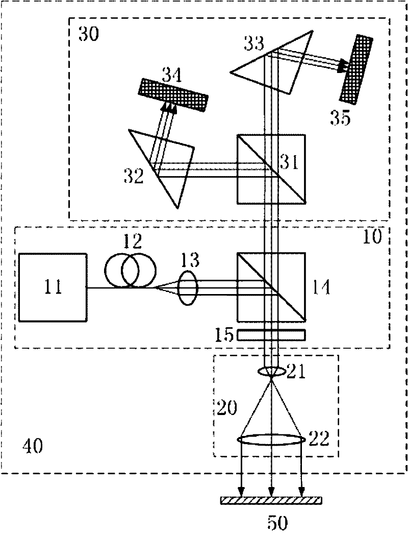
[0043] like figure 1 The shown device 40 for high-precision small-angle measurement includes: a laser emitting unit 10 , a beam expander lens unit 20 , a differential detection unit 30 , and a measuring target mirror unit 50 .

[0044] The laser emitting unit 10 includes: a laser 11 , a single-mode fiber 12 , a collimator lens 13 , a polarization beam splitter 14 and a λ / 4 wave plate 15 . Among them, the laser 11 generates the incident working beam, the single-mode fiber 12 filters its high-order mode, the collimating lens 13 collimates the working beam to obtain the reference beam, and the polarization beam splitter 14 performs polarization splitting on the reference beam to obtain the first line Polarized light (here, the reflected light, that is, the S polarized light is selected as the first linearly polarized light), and the λ / 4 wave plate 15 converts the first linearly polarized light into circularly polarized light. Laser 11, single-mode fiber 12, collimator lens 13 an...

Embodiment 2

[0070] like Figure 7 The second high-precision small-angle measurement device shown is the same as figure 1As shown, the difference is that the first linearly polarized light selects the transmitted light, that is, the P polarized light, and the P polarized light directly passes through the polarization beam splitter 14, and the optical path does not change. In this way, the laser 11, the single-mode fiber 12, the quasi-polarized light The straight lens 13, the polarizing beam splitter 14 and the λ / 4 wave plate 15 are all located on the optical path of the incident working beam, and the angle between the fast axis direction of the λ / 4 wave plate 15 and the polarization direction of the first linearly polarized light is 45°. Because the beam expander lens unit 20 is located on the optical path of the circularly polarized light obtained after the conversion of the λ / 4 wave plate 15, the measurement target mirror unit 50 is located on the outgoing optical path of the beam expand...

Embodiment 3

[0074] like Figure 8 The third high-precision small-angle measurement device is shown, and figure 1 It is similar to what is shown, and the difference is that a converging lens unit 60 is also included. The condensing lens unit 60 and the differential detection unit 30 are sequentially located on the optical path of the outgoing beam of the polarization beam splitter 14 , and the outgoing beam first passes through the condensing lens unit 60 and then enters the differential detection unit 30 .

[0075] The narrowing lens unit 60 is composed of a third convex lens 62 and a fourth convex lens 61 , and an appropriate focal length ratio (that is, reduction ratio) can be selected according to actual measurement needs.

[0076] In order to improve the stability of the working light beam and improve the resolution, in practical applications, the magnification of the beam expander lens unit 20 is usually required to be as large as possible. With the increase of the magnification of...


PUM


Abstract

The invention discloses a method and device for high-accuracy and small-angle measurement, wherein the method comprises the following steps: polarizing and splitting the reference light beam which is obtained after the collimation processing to obtain the first linearly polarized light; converting into the circularly polarized light and radiating to a measuring target mirror after the beam expansion; detecting the reverse return of the light beam which is reflected by the target mirror; carrying out the beam contraction and the secondary conversion to obtain the second linearly polarized light; polarizing and splitting the second linearly polarized light again and dividing the second linearly polarized light into the reflected light and the transmission light which have the light intensity ratio of 1 to 1; respectively radiating the two beams of light to two prisms to be reflected; and respectively receiving and processing the reflected light signals through two detectors. The device disclosed by the invention comprises a laser emitting unit, a beam expansion lens unit, a measuring target mirror unit and a differential detection unit, wherein the laser emitting unit comprises a light source, a single mode fiber, a collimation lens, a polarization splitter and a lambda/4 wave plate; and the differential detection unit comprises the splitter, the two prisms and the two detectors. The method and device disclosed by the invention have the advantages of ultrahigh accuracy and large measuring range.

Description

technical field [0001] The invention belongs to the technical field of optical measurement, and in particular relates to a non-contact high-precision small-angle measurement method and device. Background technique [0002] Angle measurement is an important part of metrology. Micro-angle measurement is of great significance in aerospace, military, precision manufacturing, high-precision testing and many other fields. At present, the commonly used optical methods for small angle measurement mainly include: self-collimation method, photoelectric coding method, circular grating method, laser interferometry, etc. Various methods have their own advantages and application limitations. Among them: laser interferometry has high precision, but the system is more complicated and expensive, and the beam cannot be blocked during the measurement process, otherwise the measurement will have to be restarted; optical self-alignment The straight method is the most widely used. Its system str...

Claims


Application Information

Patent Timeline
Patent Type & Authority Applications(China)
IPC IPC(8): G01B11/26
Inventor 匡翠方库玉龙刘旭王婷婷
Owner ZHEJIANG UNIV
Why Eureka
Try Eureka