Fluid bearing device

a technology of bearings and fluids, which is applied in the direction of bearings, shafts and bearings, rotary bearings, etc., can solve the problems of insufficient lubricant the disadvantage of reducing the shaft strength for supporting the hub, and the lubricant b>55/b> in the radial bearing portion, etc., to prevent the scattering of lubricant outside.

Active Publication Date: 2006-10-17
PANASONIC HEALTHCARE HLDG CO LTD
View PDF3 Cites 1 Cited by
  • Summary
  • Abstract
  • Description
  • Claims
  • Application Information

AI Technical Summary

Benefits of technology

[0011]The present invention is to solve the above-described problems, and has its object to provide a fluid bearing device capable of preventing a lubricant from scattering outside even during the bearing device is being driven to rotate, while holding a relatively large amount of lubricant in a seal surface portion.
[0013]According to this, a large amount of lubricant can be held because the clearance between the seal surface portion and the outer peripheral surface of the shaft can be easily made large, and the length dimension of the radial bearing portion can be taken sufficiently because the depth of the seal surface portion from the open end can be made small. Further, since the clearance from the outer peripheral surface of the shaft at the open end side end portion of the seal surface portion is smaller than the clearance at the intermediate portion, the lubricant can be prevented from scattering outside even during the bearing device is being driven to rotate, thus keeping favorable reliability.

Problems solved by technology

When the outer peripheral portion of the shaft 54 is largely notched in order to increase the lubricant-holding capacity in the seal surface portion 58, the substantial shaft diameter of the shaft 54 in this location becomes extremely small, thus causing the disadvantage of reducing the shaft strength for supporting the hub 52 and the like.
Especially, when the length of the shaft 54 itself is small as a result of reduction in size, it is difficult to form the seal surface portion 61 which can hold a sufficient amount of lubricant.
If the lubricant 55 leaks outside, there may be a threat that the lubricant 55 in the radial bearing portion 56 becomes insufficient or the hub and the like become contaminated.

Method used


Image

  • Fluid bearing device
  • Fluid bearing device
  • Fluid bearing device

Examples


Embodiment Construction

[0024]Hereinafter, embodiments of the present invention will be explained based on the drawings.

[0025]In an embodiment of the present invention shown in FIG. 1 to FIG. 4, the case in which a fluid bearing device is used as a spindle motor of a hard disk device is described, but the present invention is not limited to this.

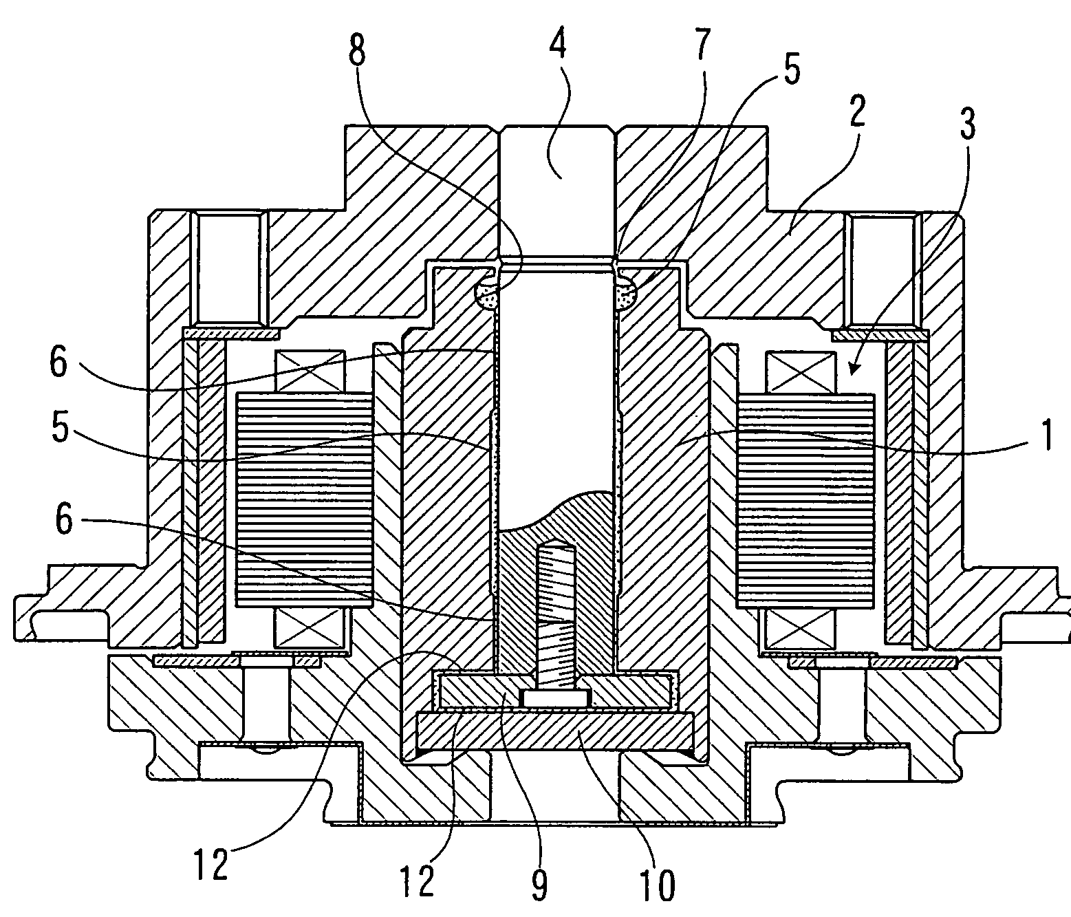
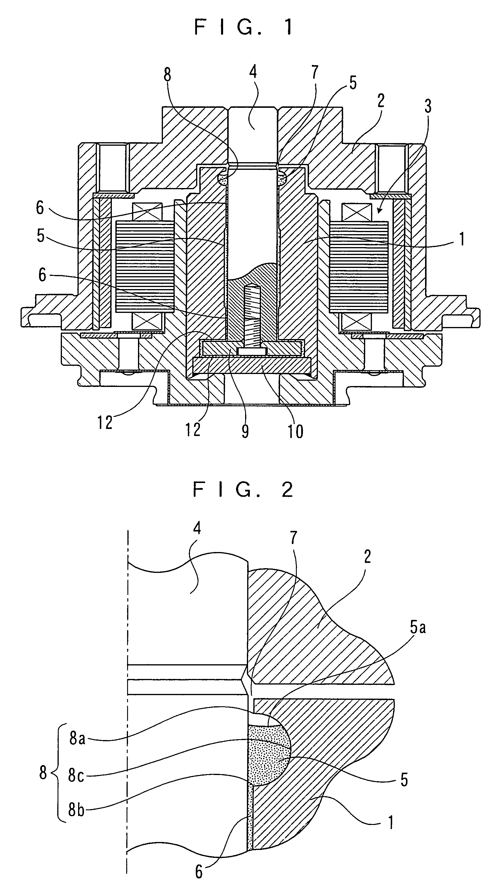
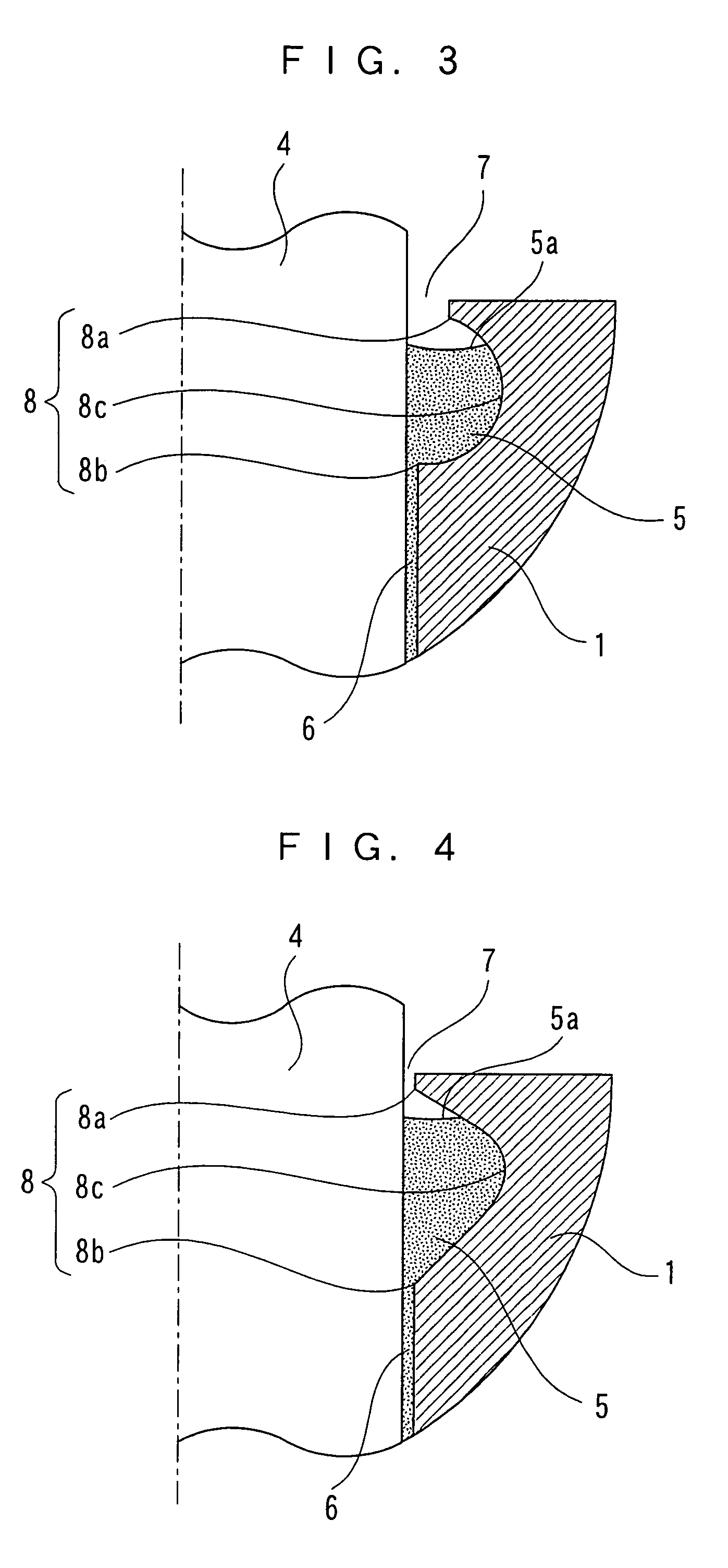
[0026]As schematically shown in FIG. 1 and FIG. 2, in this fluid bearing device, a hub 2 to which a magnetic disk is fixed is mounted to a sleeve 1 having an insertion hole in a center portion, a shaft 4 driven to rotate by a spindle motor portion 3 is inserted into the sleeve 1 via a predetermined clearance, and a lubricant 5 is filled in the clearance between the shaft 4 and the sleeve 1. A dynamic pressure generating groove in a herringbone shape or the like is formed on at least one of an outer peripheral surface of the shaft 4 and an inner peripheral surface of the sleeve 1 in the surfaces opposing to each other to construct radial bearing portions 6, and the ...


PUM


Abstract

A fluid bearing device for preventing a lubricant from scattering outside even during rotation thereof, while holding a relatively large amount of lubricant in a seal surface portion. Lubricant is filled between a sleeve and a shaft, the seal surface portion is formed in a location facing an open end of the sleeve, a sectional shape of the seal surface portion is such that a smallest clearance from an outer peripheral surface of the shaft is at a radial bearing portion side end portion of the seal surface portion, a largest clearance is at an intermediate portion between the radial bearing portion side end portion and an open end side end portion of the seal surface portion, and a clearance at the open end side end portion of the seal surface portion is smaller than the clearance at the intermediate portion.

Description

FIELD OF THE INVENTION[0001]The present invention relates to a fluid bearing device suitable for a spindle motor of a hard disk device or the like. The fluid bearing device of the present invention is suitable as a fluid bearing device for motors of a video tape recorder and the like, in addition to a spindle motor of a hard disk device and so forth. Further, the fluid bearing device of the present invention can be used as a bearing for supporting other rotary parts.BACKGROUND OF THE INVENTION[0002]With an increase in capacity of a hard disk device of recent years, a number of fluid bearing devices, which are more excellent in rotational accuracy than a ball bearing and excellent in noiselessness, are being used as bearing devices for spindle motors of hard disk devices and the like, in place of ball bearing devices conventionally used.[0003]In this type of conventional fluid bearing device, as schematically shown in FIG. 6 and FIG. 7, a hub 52 to which a magnetic disk is fixed is m...

Claims


Application Information

Patent Timeline
Patent Type & Authority Patents(United States)
IPC IPC(8): F16C17/02F16C33/10F16C33/74
CPCF16C33/74
Inventor HAGA, TOMOHIRO
Owner PANASONIC HEALTHCARE HLDG CO LTD
Why Eureka
Try Eureka