
Fan and motor thereof

a technology of a fan and a motor, which is applied in the direction of instruments, recording information storage, and recording on magnetic disks, etc., can solve the problems of reducing the life of the motor, limiting the application of the fan, and the inability to efficiently increase the rotation speed of the fan b>1/b>b, so as to reduce noise and vibration, and stabilize the rotation

Active Publication Date: 2014-10-07
DELTA ELECTRONICS INC
View PDF15 Cites 1 Cited by
  • Summary
  • Abstract
  • Description
  • Claims
  • Application Information

AI Technical Summary

Benefits of technology

The configuration significantly reduces noise, vibration, and component abrasion, improving the motor's stability and application across different rotation speeds and environments.

Problems solved by technology

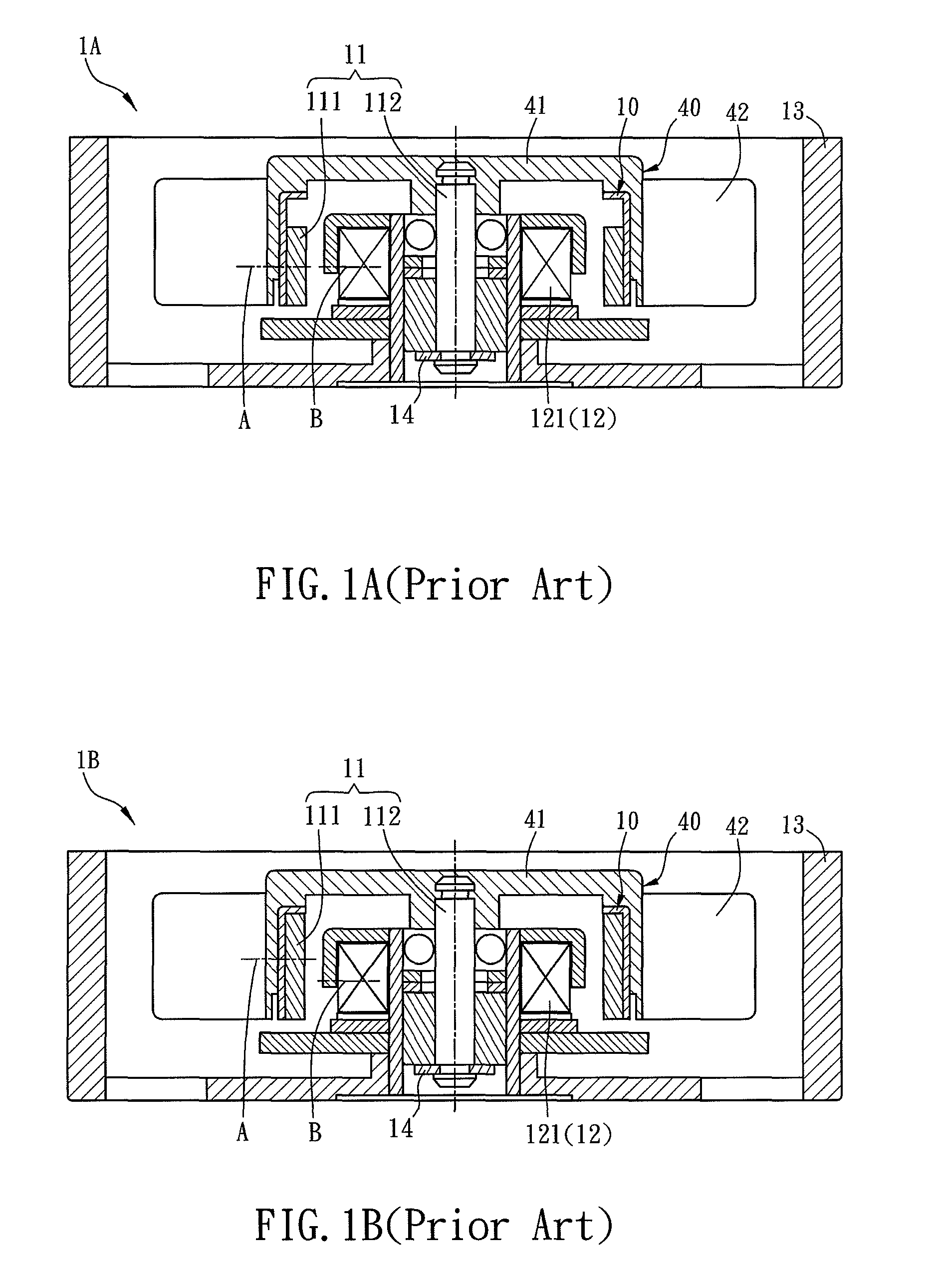
This may cause the noise of the fan 1A in the operation, and the abrasion of the connecting ring 14 or other components, thereby shortening the lifetime of the motor 10.
If the motor is upside down, the misaligned configuration for the fan 1B can not provide proper force to pull the rotor 11, which sufficiently restricts the application of the fan 1B.
Besides, since some energy is transformed to the reacting force for pushing the rotor 11 upwardly, the rotation speed of the fan 1B can not be efficiently increased.

Method used


Image

  • Fan and motor thereof
  • Fan and motor thereof
  • Fan and motor thereof

Examples


Embodiment Construction

[0029]The present invention will be apparent from the following detailed description, which proceeds with reference to the accompanying drawings, wherein the same references relate to the same elements.

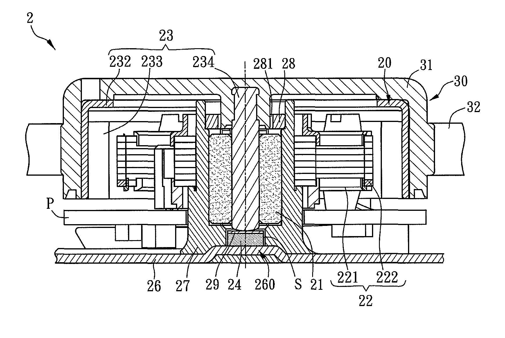
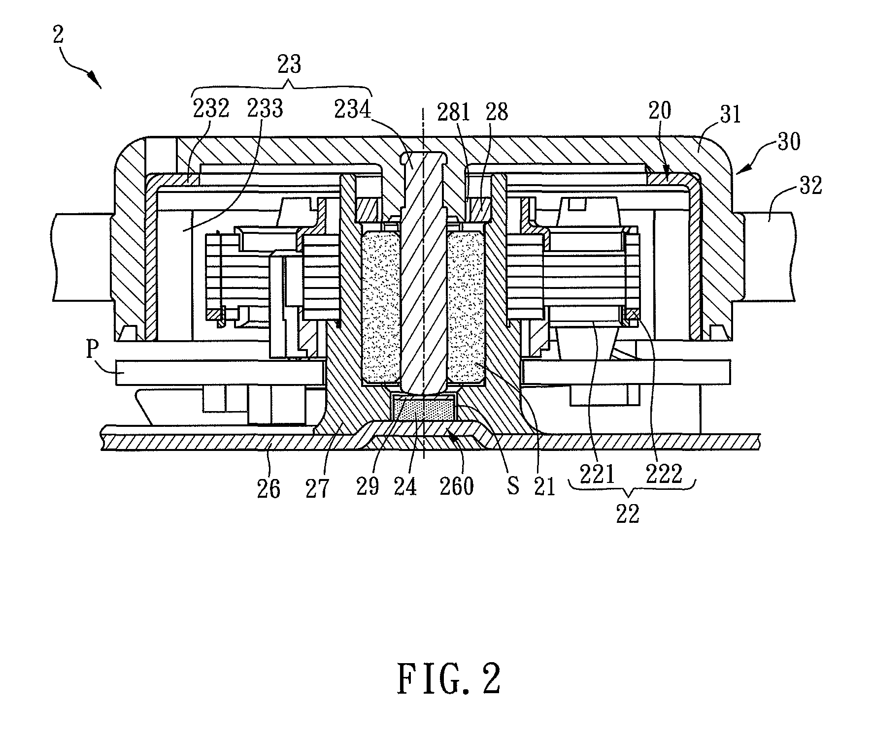
[0030]FIG. 2 is a schematic diagram showing a fan 2 and a motor 20 thereof according to an embodiment of the invention. Referring to FIG. 2, the fan 2 includes a motor 20 and an impeller 30. The motor 20 connects to the impeller 30 for driving the impeller 30 to rotate. The fan can be an axial-flow fan or a centrifugal fan. In the following embodiments, the fan is, for example but not limited to, the axial-flow fan. The impeller 30 includes a hub 31 and a plurality of blades 32. In details, the motor 20 connects to the hub 31. When the motor 20 drives the hub 31 to rotate, the rotating blades 32 can induce the airflow. Since the structure and operation of the fan composed of the motor and the impeller are the well-known technology for those skilled in the art, the detailed description...


PUM


Abstract

A motor includes a base, a bushing, a bearing structure, a stator structure, a rotor structure and a magnetic element. The base has a supporting platform. The bushing is connected with the base. The bearing structure is disposed in the bushing. The bushing is threaded through the stator structure. The rotor structure has a shaft, and the shaft threads through the bearing structure. The magnetic element corresponds to the shaft and is disposed on the supporting platform, and the magnetic element magnetically interacts with the shaft. A fan equipped with the motor is also disclosed.

Description

CROSS REFERENCE TO RELATED APPLICATIONS[0001]This Non-provisional application claims priority under 35 U.S.C. §119(a) on Patent Application No(s). 100109281 filed in Taiwan, Republic of China on Mar. 18, 2011, the entire contents of which are hereby incorporated by reference.BACKGROUND OF THE INVENTION[0002]1. Field of Invention[0003]The present invention relates to a fan and a motor thereof. In particularly, the present invention relates to a fan and a motor thereof configured with a magnetic element for magnetically attaching to the shaft so as to stable the rotation of the shaft.[0004]2. Related Art[0005]FIG. 1A is a schematic diagram showing a conventional fan 1A and its motor 10. The fan 1A includes a motor 10 and an impeller 40. The motor 10 connects to the impeller 40 for driving it to rotate. The impeller 40 has a hub 41 and a plurality of blades 42. The motor 10 has a rotor 11, a stator 12 and a frame 13. The rotor 11 is connected to the stator 12 through a connecting ring ...

Claims


Application Information

Patent Timeline
Patent Type & Authority Patents(United States)
IPC IPC(8): H02K5/16H02K5/167
CPCH02K5/1675
Inventor WU, CHIH-HUI
Owner DELTA ELECTRONICS INC
Learn More