Motor having magnetic fluid bearing structure

Inactive Publication Date: 2008-05-22
DELTA ELECTRONICS INC
View PDF3 Cites 7 Cited by
  • Summary
  • Abstract
  • Description
  • Claims
  • Application Information

AI Technical Summary

Benefits of technology

[0013]As mentioned above, the motor having the magnetic fluid bearing structure according to the invention prevents the lubricant of the bearing from leaking according to the magnetic fluid accommodated between the bearing and the shaft and the magnetic effect between the magnetic element and the magnetic fluid. In addition, the generated hydraulic pressure provides the additional axial and radial supports to make the shaft rotate steadily relative to the bearing. Compared with the related art, the magnetic fluid of the invention generates

Problems solved by technology

However, the oil seal 14 is mounted around the shaft 12 and the space for storing the lubricant cannot be completely se

Method used


Image

  • Motor having magnetic fluid bearing structure
  • Motor having magnetic fluid bearing structure
  • Motor having magnetic fluid bearing structure

Examples


first embodiment

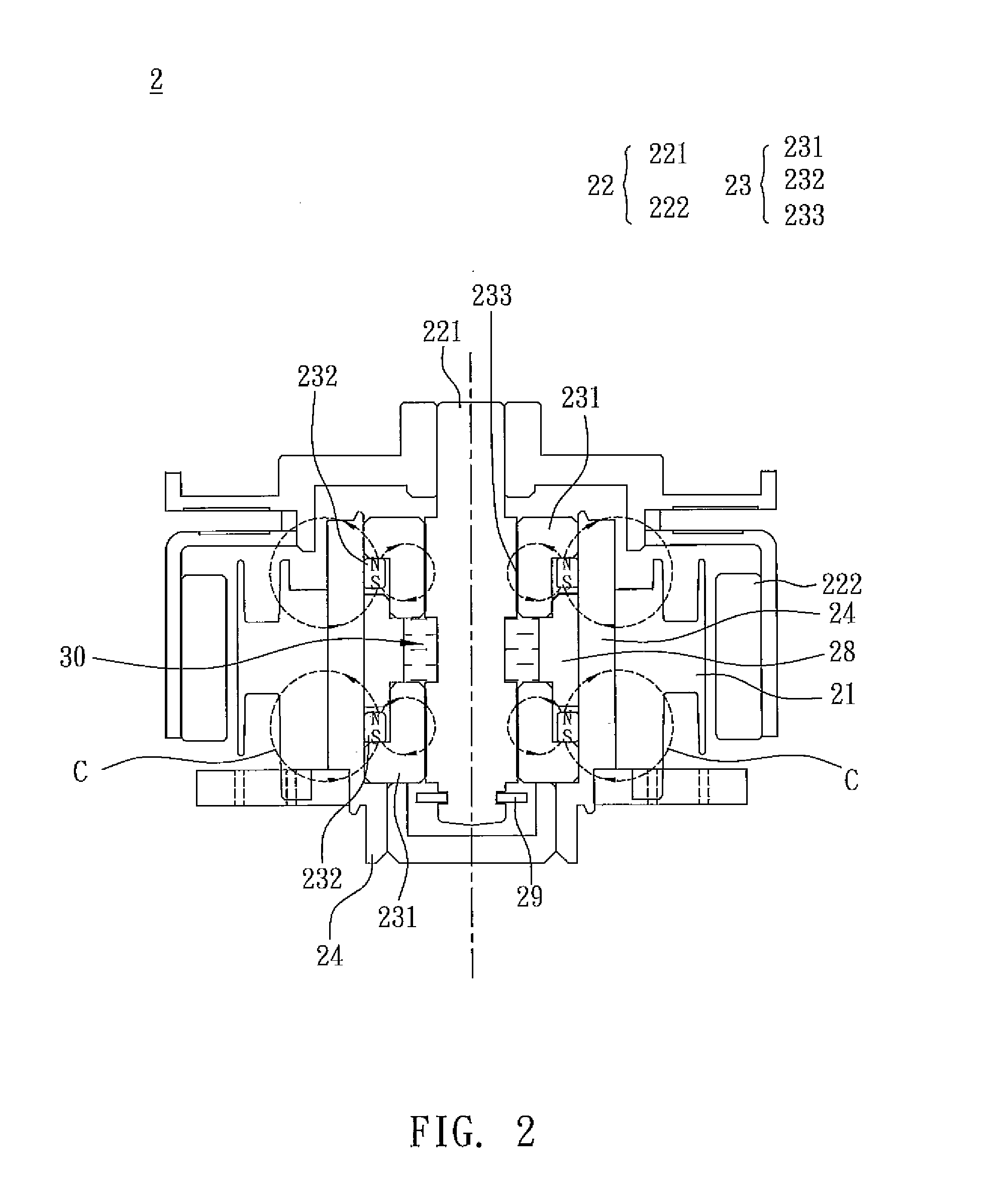
[0030]As shown in FIG. 2, a motor 2 according to the invention includes a rotor 22, a stator 21 and a magnetic fluid bearing structure 23. The rotor 22 has a shaft 221 and a magnet 222. In this embodiment, the shaft 221 does not have the magnetic-conducting property. The stator 21 is disposed corresponding to the rotor 22, and between the magnet 222 and the shaft 221. The magnetic fluid bearing structure 23 includes at least one bearing 231, at least one magnetic element 232 and magnetic fluid 233. In this embodiment, the magnetic fluid bearing structure 23 has two bearings 231 and two magnetic elements 232. Each of the magnetic elements 232 can be, without limitation to, a permanent magnet, an electronic magnet or a magnet. The magnetic fluid 233 can contain iron, cobalt, nickel or alloys thereof.

[0031]The motor 2 further includes a first positioning element 28 and a second positioning element 29. The first positioning element 28 has the magnetic-conducting property or does not hav...

second embodiment

[0033]As shown in FIG. 3, the structure and the function of a motor 2a according to the invention are the same as those of the motor 2 except that the N and S poles of each magnetic element 232a are arranged radially with respect to the shaft 221. Therefore, a magnetic loop C1 thereof is distributed radially with respect to the shaft 221. Because each of the bearings 231 has the magnetic-conducting property, the magnetic loops C1 formed by the magnetic elements 232a can attract the magnetic fluid 233 through the bearings 231 when the motor 2a is rotating. In addition, the magnetic loops C1 are in direct proportion to the magnetic flux density to radially provide the lubrication and supporting functions between the bearings 231 and the shaft 221, thereby decreasing the wear of each of the shaft 221 and the bearings 231, and equivalent to the oil seal structure to avoid the lubricant consumption.

[0034]Referring to FIG. 4, a motor 3 according to a third embodiment of the invention are ...

fourth embodiment

[0036]As shown in FIG. 5, the structure and the function of a motor 3a according to the invention are the same as those of the motor 3 shown in FIG. 4 except that the N and S poles of a magnetic element 332a are arranged radially with respect to the shaft 221 in a magnetic fluid bearing structure 33a of this embodiment. Thus, a magnetic loop C3 is distributed radially with respect to the shaft 221. Because each of the bearings 331 and the shaft 221 has the magnetic-conducting property, the magnetic loop C3 formed by the magnetic element 332a can attract the magnetic fluid 333 to the contact surface between the shaft 221 and the bearings 331, and is in direct proportion to the magnetic flux density to radially provide the lubrication and supporting functions between the bearings 331 and the shaft 221. Thus, the wear of each of the shaft 221 and the bearings 331 can be decreased to avoid the lubricant consumption.


PUM


Abstract

A motor having a magnetic fluid bearing structure, which includes at least one bearing, at least one magnetic element and a magnetic fluid. The bearing is telescoped onto a shaft, and the magnetic element is coupled to the bearing. The magnetic fluid is kept between the bearing and the shaft. According to a magnetic effect between the magnetic fluid and the magnetic element, it is possible to prevent a lubricant of the bearing from leaking, and a hydraulic pressure of the magnetic fluid provides additional axial and radial supports to make the shaft rotate steadily relative to the bearing.

Description

CROSS REFERENCE TO RELATED APPLICATIONS[0001]This Non-provisional application claims priority under 35 U.S.C. §119(a) on Patent Application No(s). 095142581, 095142582 and 095142583 filed in Taiwan, Republic of China on Nov. 17, 2006, and the Patent Application No 096119480 filed in Taiwan, Republic of China on May 31, 2007, the entire contents of which are hereby incorporated by reference.BACKGROUND OF THE INVENTION[0002]1. Field of Invention[0003]The invention relates to a motor and, in particular, to a motor having a magnetic fluid bearing structure.[0004]2. Related Art[0005]In response to the smoothness and the stability of the motor at a high rotating speed, a bearing is conventionally used to support a shaft. Referring to FIG. 1, a conventional motor 1 includes a stator 11, a shaft 12, a bearing 13 and an oil seal 14. The bearing 13 is a sleeve bearing, and the oil seal 14 can be a loop or a metal ring. The oil seal 14 is disposed above the bearing 13 and is mounted around the...

Claims


Application Information

Patent Timeline
IPC IPC(8): H02K7/09F16C33/10H02K5/128
CPCF16C17/10H02K7/085H02K7/09F16C33/1035
Inventor CHANG, SEANCHANG, CHII-HOWLAI, CHIN-CHUNCHEN, LI-MINGYU, CHING-HSIANGWU, CHIA-CHI
Owner DELTA ELECTRONICS INC
Why Eureka
Try Eureka